 English
 Le français
 Türkçe





A packaging laminating machine has two separate motor duties, and they are not sized by the same rule. The main drive turns the coating and laminating rolls at line speed with constant torque; the winder and unwinder motors must keep film tension constant while the roll diameter grows or shrinks. On the main drive the deciding factors are speed stability and threading torque at low speed; on the winder they are the diameter ratio and the highest torque at full roll.
DRG Motor is a manufacturer, supplier and seller of electric motors; the inverter-driven 4-pole three-phase asynchronous motors used on laminating lines are listed on the buy electric motors online page. Drives, servo motors and gearboxes are outside DRG's product range; DRG supplies the line's standard IEC asynchronous motors.
For other drives on packaging and converting machines, see the paper and board converting machine motors page.
Which Roll Does What on a Laminating Line?
On a typical film laminator, the film from the first unwinder (for example printed BOPP or PET) enters the coating unit. On a solvent-based machine the adhesive is applied by a gravure roll wiped by a doctor blade, and the film passes through a drying tunnel; on a solventless machine the adhesive is thinned between metering rolls turning at different speeds and transferred to the film. The film from the second unwinder (for example PE or aluminium foil) is then pressed onto the first between a heated steel roll and a rubber nip roll, and the two-layer material is wound into a roll on the winder.
The main drive motor turns the coating and laminating rolls by belt, gearbox or line shaft and is the line's speed reference. The unwinders and the winder follow that speed under tension control. Even a small fluctuation in roll surface speed causes layer shift, wrinkles or web breaks in the tunnel.
Main Drive: From Line Speed to Roll Speed and Torque
The figures that follow are an example of method. Real roll torque depends on doctor blade friction, nip roll force and film tension; for the actual figure, refer to the nameplate or catalogue of whoever built the machine.
Example assumptions: maximum line speed 200 m/min, laminating roll diameter 250 mm, total torque at the roll shaft 80 Nm, transmission efficiency 0.9.
- Roll speed: n = 200 / (π × 0.25) ≈ 254.6 rpm.
- Required ratio (4-pole motor, 1450 rpm): i ≈ 5.69.
- Roll power: 80 × 254.6 / 9550 ≈ 2.13 kW; with transmission losses ≈ 2.37 kW at the motor.
- Torque needed at the motor shaft: 80 / (5.69 × 0.9) ≈ 15.6 Nm.
For this load the DRG-100L2-4 (3 kW, 1450 rpm, rated torque 19.8 Nm) is a suitable starting point. During film threading and set-up the line drops to 10–20 m/min; in that range the motor turns at constant torque at about 2.5–5 Hz. Short threading speeds are no problem, but if the line produces at low speed for long periods, taking the motor one size up leaves a margin for heating. For the ratio on a belt drive, use the pulley and belt calculator.
On small narrow-web machines the main drive stays at a few kW; on wide, fast lines the coating and laminating units are driven by separate motors and total power rises markedly.
Click to see current electric motor prices and order nowSEE PRICES →
Winder Motor: How Does the Diameter Ratio Increase Torque?
On a centre-driven winder, with film tension held constant, roll torque grows in proportion to diameter while roll speed falls in inverse proportion. Power (tension × speed) does not change, but the motor must handle both low torque at very high speed and high torque at very low speed. The winder motor is therefore sized for torque at full roll, not for the power delivered to the film.
Example (assumption): film tension 250 N, line speed 200 m/min, core diameter 76 mm, full roll diameter 800 mm, winder ratio i = 3.46, transmission efficiency 0.95. Power delivered to the film is only 250 × 200 / 60 ≈ 833 W.
| Roll diameter (mm) | Roll torque (Nm) | Motor speed (rpm) | Motor torque / frequency |
|---|---|---|---|
| 76 (empty core) | 9.5 | 2898 | 2.9 Nm / ~100 Hz |
| 200 | 25 | 1101 | 7.6 Nm / ~38 Hz |
| 400 | 50 | 551 | 15.2 Nm / ~19 Hz |
| 800 (full roll) | 100 | 275 | 30.4 Nm / ~9.5 Hz |
Here the ratio is deliberately chosen so that on the empty core the motor runs at about 100 Hz (in the field-weakening range). Above 50 Hz the torque the motor can deliver falls in inverse proportion to frequency, but the torque needed at the core is very small anyway. In this way the 10.5 times diameter ratio is spread over the motor's speed range. For operation above 50 Hz, the maximum speed permitted by the motor and transmission must be confirmed with the order.
For the 30.4 Nm at full roll, the DRG-132S-4 (5.5 kW, 36.0 Nm) is at its limit; near full roll the motor runs for long periods around 10 Hz with high torque while its shaft fan turns slowly. The DRG-132M-4 (7.5 kW, 49.1 Nm) therefore gives a safer margin. Choosing a 5.5–7.5 kW motor for 0.83 kW of film power is a natural result of this load type, not a calculation error. Keeping the ratio close to 1:1 (i ≈ 1.73) would double the motor torque at full roll.
Heated Roll, Solvent Vapour and Line Conditions
The laminating roll is usually a steel roll with hot water or thermal oil flowing inside, heated according to the adhesive type. Heat can pass from the roll bearings and frame into the motor flange; do not place the main drive motor directly under the heated roll or facing the drying tunnel exhaust. The motors' rated ambient range is −15…+40 °C.
On solvent-based lamination there is solvent vapour around the coating unit and drying tunnel. Where the site has zoned this area for explosive atmospheres, no standard IEC motor may run inside it; that position calls for an Ex-protected special motor, which is outside the DRG range. Winder, unwinder or tunnel fan motors outside the zone can use standard motors. Solventless machines usually do not have this restriction, but the area around the adhesive mixing unit should still be assessed.
Edge trim knives produce fine plastic dust and trim strips. If this waste catches on the fan cover grille the motor heats up; especially on a winder motor that runs long at low speed, the fan cover must be cleaned regularly.
Mounting and Connection Checks When Replacing a Motor
On most machines the main drive motor is foot-mounted (B3) and belted to the roll shaft; winder and unwinder motors may connect to a gearbox with a B5 flange or foot and flange (B35). Relevant dimensions in the DRG catalogue:
- Frame 90L: shaft 24 × 50 mm, foot holes A 140 / B 125 mm, B5 flange M 165 / N 130 / P 200 mm.
- Frame 100L: shaft 28 × 60 mm, foot holes A 160 / B 140 mm, B5 flange M 215 / N 180 / P 250 mm.
- Frames 132S and 132M: shaft 38 × 80 mm, A 216 mm; B is 140 mm on 132S and 178 mm on 132M; B5 flange M 265 / N 230 / P 300 mm.
Moving from 132S to 132M keeps the shaft height (132 mm) and flange the same, but the foot hole spacing grows from 140 to 178 mm; foot mounting needs new holes in the base. Motors up to 3 kW are wound 230/400 V, 4 kW and above 400/690 V; connect to the drive output (Δ / Y) as per the nameplate and enter the motor's rated current and speed correctly in the drive.
Faults Seen on a Laminating Line After a Wrong Choice
- Tension drops as the roll grows and the roll winds loose: the winder motor has hit its torque limit at full roll.
- The winder cannot keep up on the empty core: the ratio is too large and the motor cannot reach the required speed.
- Layer shift during acceleration and deceleration: the main drive loses speed under acceleration; motor or drive ramp setting is insufficient.
- The winder motor is very hot at the end of the shift: it runs long at low frequency with high torque.
- Periodic lines in coating thickness: belt slip, or play between motor shaft and pulley.
Checklist before replacement or order:
- The motor's duty: main drive, winder, unwinder or tunnel fan.
- Photo of the motor nameplate (kW, rpm, voltage, current).
- Highest and lowest line speed (m/min) and roll diameter.
- For the winder: core diameter, largest roll diameter and film tension.
- Transmission: belt and pulley ratio or gearbox ratio.
- Mounting (B3, B5, B35) and shaft size.
- Whether the motor sits in the solvent zone.
DRG Motors Suited to Laminating Machine Drives
These are 4-pole cast iron motors suitable for inverter drive, covering the main drive (3 kW) and winder (5.5–7.5 kW) duties of the example calculations as well as smaller unwinder drives.
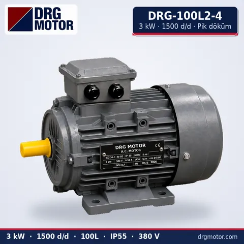
3 kW Three-Phase Motor 1500 rpm – DRG-100L2-4 Cast Iron
- 3 kW · 1500 rpm (4 poles)
- Cast iron frame · IEC 100L
- Mounting: B3 · B5 · B14 · B35
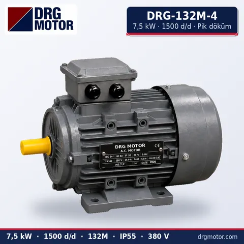
7.5 kW Three-Phase Motor 1500 rpm – DRG-132M-4 Cast Iron
- 7.5 kW · 1500 rpm (4 poles)
- Cast iron frame · IEC 132M
- Mounting: B3 · B5 · B14 · B35
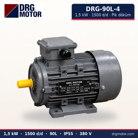
1.5 kW Three-Phase Motor 1500 rpm – DRG-90L-4 Cast Iron
- 1.5 kW · 1500 rpm (4 poles)
- Cast iron frame · IEC 90L
- Mounting: B3 · B5 · B14 · B35
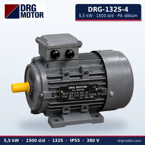
5.5 kW Three-Phase Motor 1500 rpm – DRG-132S-4 Cast Iron
- 5.5 kW · 1500 rpm (4 poles)
- Cast iron frame · IEC 132S
- Mounting: B3 · B5 · B14 · B35
Click to see current prices and order these motors nowSEE PRICES →
Laminating Machine Motor: Frequently Asked Questions
Why is the winder motor bigger than the main motor on a laminator?
The winder has to deliver the high torque of a full roll at low speed. Although film power is small, the motor is sized for that peak torque and so often turns out larger than the main drive.
Is a servo mandatory instead of an asynchronous motor on a laminating line?
No. Asynchronous motors with a tension-controlled drive (dancer or load-cell feedback) are used on many lines. Servo is preferred on very high-speed lines that need precise register; DRG does not supply servo motors.
Does the heated laminating roll affect the motor?
Not directly; heat reaches it through the bearings and frame. The motor's ambient temperature must not exceed 40 °C; place it away from the heat source with the front of the fan cover clear.
What kW is the main motor of a laminating machine?
It depends on web width, speed and the number of units; small narrow-web machines use a few kW, wide lines more. When replacing, the rule is to choose a motor with the same power and speed as the nameplate.
To request a quote, share the nameplate photo together with power, speed, foot or flange mounting, shaft size and which laminator duty the motor serves (main drive, winder, unwinder) on WhatsApp, or build a request through the quote list. You can also call +90 (542) 666 11 11, write to info@drgmotor.com or use the contact page. The complete motor range is listed in the online store.





