 English
 Le français
 Türkçe




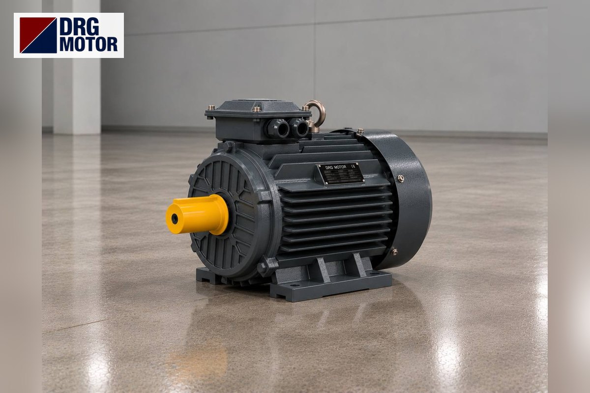

In a biscuit tunnel oven the band drive motor turns the drive drum at the oven exit very slowly through a gearbox, pulling the steel or wire mesh band, with the dough pieces on it, through the oven. Band speed sets the baking time; that is why the motor is almost always run from an inverter, and what decides the choice is its ability to give enough torque to pull the band at low band speed too. The oven builder sets the power from oven length, band width and weight: short ovens use motors of a few kW, long lines larger ones.
DRG Motor is a manufacturer, supplier and seller of electric motors; it supplies not the oven or the gearbox but the three-phase asynchronous IEC motor that connects to the gearbox. Models of suitable power and speed are on the buy electric motors online page. For an overview of fan and band motors on oven lines, see the industrial bakery oven electric motors page.
How Does the Band Move in a Tunnel Oven?
Biscuit dough leaves the forming machine, is laid out on the band and enters the oven mouth with it. The band forms an endless loop between large drums at both ends of the oven: the upper strand carries the product through the oven, the lower strand returns underneath. The drive is usually on the exit drum; the band is pulled, not pushed. The entry drum is part of the take-up that keeps the band tight.
The band lengthens as it heats. The take-up absorbs this growth and prevents slip on the drive drum. Tracking rollers also keep the band centred on the drums. If these systems fail, the motor has no trouble pulling, but the band slips or runs off to one side; the motor is not where the fault lies.
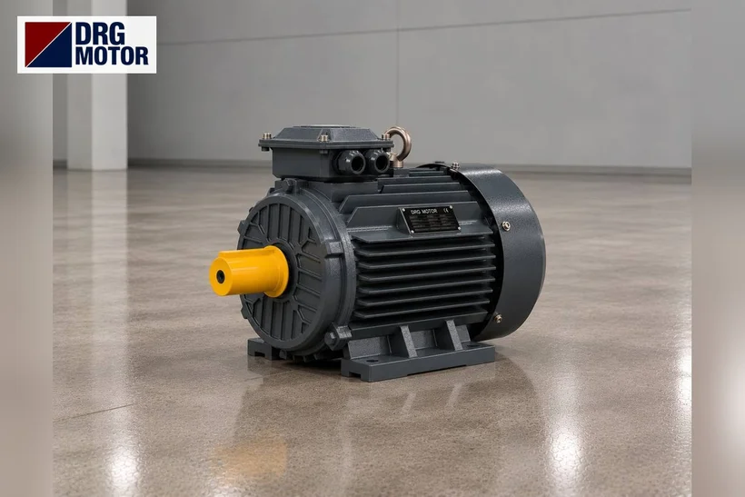
Baking Time, Band Speed and Frequency
Baking time is the oven length divided by band speed. When the product changes, the operator changes baking time, which means changing frequency on the inverter. The table below is an example: a 30 m oven, a Ø600 mm drive drum and a transmission ratio giving a top band speed of 12 m/min at 50 Hz are assumed.
| Baking time | Band speed | Drum speed | Inverter frequency |
|---|---|---|---|
| 2.5 min | 12 m/min | 6.37 rpm | 50 Hz |
| 3.3 min | 9 m/min | 4.77 rpm | 37.5 Hz |
| 5.0 min | 6 m/min | 3.18 rpm | 25 Hz |
| 7.5 min | 4 m/min | 2.12 rpm | 16.7 Hz |
| 10.0 min | 3 m/min | 1.59 rpm | 12.5 Hz |
Because the drum turns at a few rpm, the overall ratio is very large: for 12 m/min, about 228 with a 4-pole 1450 rpm motor and about 150 with a 6-pole 955 rpm motor. This ratio is often provided not by one gearbox alone but by a gearbox plus a chain drive. To test ratio and output speed with your own figures, use the gearbox output speed and torque calculator.
Cooling at low frequency
A band drive is a constant-torque load: even as the band slows, the force needed to pull it stays almost the same. DRG motors are self-ventilated (IC411); since the fan is on the motor shaft, cooling air drops markedly in the 12–17 Hz range. If the oven will run in this range for long periods, either choose the ratio so that the motor turns at 30–50 Hz, or choose a motor large enough to be loaded below its rated torque.
Click to see current electric motor prices and order nowSEE PRICES →
Torque Calculation: an Example Band
Band pull depends on band weight, product load, friction on the slide beds and take-up force. The real value is in the oven builder's calculation. The numbers below only illustrate the method.
Example: assume a pull of 6000 N at the drive drum and a Ø600 mm drum. Drum torque is 6000 × 0.3 = 1800 Nm; at 6.37 rpm the drum power is about 1.20 kW. Assuming an overall gearbox and chain efficiency of 0.7, about 1.71 kW is needed on the motor side.
Under the same assumption the rated torque the motors can deliver at the drum is: DRG-90L-4 (1.5 kW, 9.91 Nm) about 1575 Nm, DRG-100L1-4 (2.2 kW, 14.5 Nm) about 2312 Nm. The 6-pole equivalents DRG-100L-6 and DRG-112M-6 reach the same drum torque with a lower ratio. In this example 1.5 kW is borderline; 2.2 kW leaves margin both at start and at low frequency.
Gearbox and Connection Dimensions
The drive drum usually takes a hollow-shaft gearbox mounted on the drum shaft, or a foot-mounted gearbox with a chain; the motor sits on the gearbox input with a flange. DRG does not sell gearboxes; it supplies the motor that fits them. For general selection of motors on gearbox inputs see the electric motors for gearboxes page.
B5 flange dimensions from the catalogue: frame 90L has bolt circle M 165 mm, spigot N 130 mm, flange outside diameter P 200 mm and a 24×50 mm shaft. Frames 100L and 112M have M 215, N 180, P 250 mm and a 28×60 mm shaft. If the gearbox input is a small flange (B14), dimensions are confirmed at order.
Oven Heat and Motor Location
DRG motors are rated for an ambient temperature of −15…+40 °C. As the drive drum is at the oven exit, hot air and product vapour can reach the motor. Motor and gearbox should sit away from the oven mouth, in open air or on the outer side of the drum; heat radiating from the oven body should not hit the motor frame directly. If ambient exceeds 40 °C, the answer is not a different motor but moving or ventilating it.
Biscuit crumbs, fat vapour and flour build up on the fan cover. IP55 protects against dust and water splashes; in areas washed with pressurised water the motor must be shielded.
The other bands of the line
Ahead of the oven band there is a feed conveyor, and after it cooling and packing conveyors. Each usually runs on its own motor and inverter, with speeds set relative to the oven band. If a replacement oven motor has a different speed, synchronisation with the other bands is lost; product jams at transfers or gaps open up.
Before Replacing the Band Motor
- Motor nameplate: power, speed, voltage, rated current
- Gearbox ratio, input flange type (B5/B14) and shaft size
- Chain sprocket tooth counts and drum diameter
- Lowest and highest inverter operating frequency
- Ambient temperature where the motor sits
- Are the take-up and tracking rollers working?
- Speeds and motors of the feed and cooling conveyors
Common mistakes: replacing a 4-pole motor with a 6-pole one and lowering band speed at the same frequency; mistaking band slip for a weak motor and increasing power; mounting the motor near the oven mouth in the hot zone; not setting the inverter to the motor's rated current.
DRG Motors Suited to Biscuit Oven Band Drives
1.5 and 2.2 kW, 4- and 6-pole aluminium-housing models for the gearbox input; wound for 230/400 V, they are connected in star on a 400 V supply and on an inverter output.
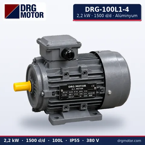
2.2 kW Three-Phase Motor 1500 rpm – DRG-100L1-4 Aluminium
- 2.2 kW · 1500 rpm (4 poles)
- Aluminium frame · IEC 100L
- Mounting: B3 · B5 · B14 · B35
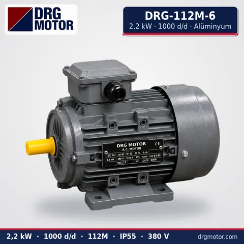
2.2 kW Three-Phase Motor 1000 rpm – DRG-112M-6 Aluminium
- 2.2 kW · 1000 rpm (6 poles)
- Aluminium frame · IEC 112M
- Mounting: B3 · B5 · B14 · B35
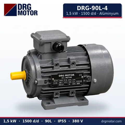
1.5 kW Three-Phase Motor 1500 rpm – DRG-90L-4 Aluminium
- 1.5 kW · 1500 rpm (4 poles)
- Aluminium frame · IEC 90L
- Mounting: B3 · B5 · B14 · B35
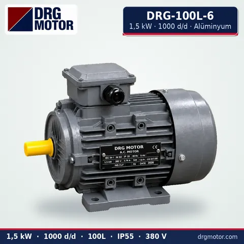
1.5 kW Three-Phase Motor 1000 rpm – DRG-100L-6 Aluminium
- 1.5 kW · 1000 rpm (6 poles)
- Aluminium frame · IEC 100L
- Mounting: B3 · B5 · B14 · B35
Click to see current prices and order these motors nowSEE PRICES →
Biscuit Oven Band Motor: Frequently Asked Questions
What speed should a tunnel oven band motor have?
The motor itself is usually in the 1500 rpm (4-pole) or 1000 rpm (6-pole) class; the drum's few rpm are reached through a gearbox and chain. Keeping the old motor's pole number at replacement gives the same band speed without changing ratios.
Why is a biscuit oven band driven by an inverter?
Baking time is set by band speed, and each product needs a different time. Besides speed control, the inverter starts the band smoothly and synchronises it with the other conveyors. The inverter is sourced separately; DRG does not sell inverters.
The motor gets hot when the band is slow; why?
At low frequency the shaft fan slows down, but the torque the band needs does not fall. If the motor is near its rated load it overheats. Changing the ratio so the motor runs at a higher frequency, or choosing a larger motor, is the remedy.
On which side should the oven band motor be?
On most ovens it is on the exit drum, since the band is pulled. Motor and gearbox should sit on the outer side of the drum, away from the hot oven mouth.
For a quote, send a photo of the motor nameplate with power, speed, flange or foot mounting, shaft size, gearbox ratio and inverter frequency range via WhatsApp, or add the models to the quote list. Phone +90 (542) 666 11 11, e-mail info@drgmotor.com, more on the contact page. All models and current prices are in the online shop.





