English
 Le français
 Türkçe




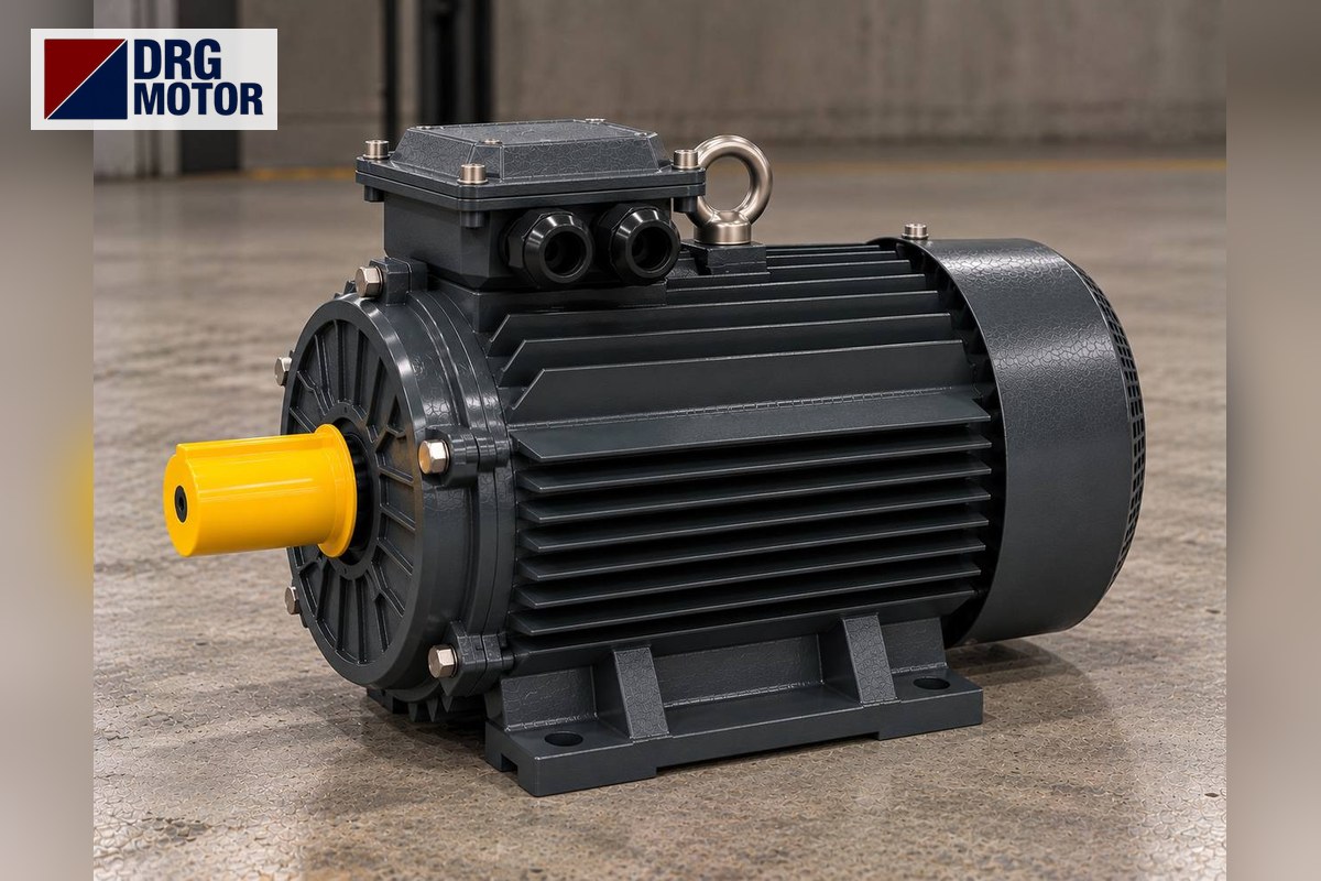

If a foot-mounted (B3) WEG W22 electric motor is to be removed and replaced, most of the work concerns the base it sits on: will the holes line up, will the shaft stay at the same height, will the coupling meet at the same distance? This article explains which mounting dimensions of your W22 B3 motor to measure, in which order and how, and how to send them to DRG MOTOR.
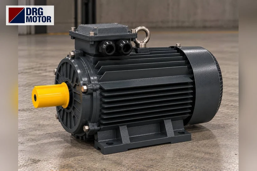
Foot-mounted design and the B3T code on the W22
According to WEG's European catalogue, the standard W22 mounting is foot-mounted B3T; the catalogue also distinguishes the terminal box position with codes such as B3R, B3L and B3T. Mounting arrangements are defined according to IEC 60034-7. So check whether your motor is designated with a mounting other than B3 (e.g. B35) on the plate or order code. Photograph whether the terminal box is on top, right or left, as cable routing and access depend on it.
Foot and shaft values to measure
The letters in the catalogue's foot-mounted dimension table follow general IEC usage. For base compatibility, measure:
- H – shaft height: from the foot underside to the shaft centre; the frame number indicates it (112, 132, 160...).
- A – transverse hole spacing: between hole centres of the two feet, perpendicular to the shaft.
- B – longitudinal hole spacing: between front and rear hole centres on the same side.
- C – shaft shoulder to front hole: directly affects coupling or pulley alignment.
- K – hole diameter: sets the bolt size.
- D×E – shaft diameter and length, plus key width.
Measure from hole centres, not hole edges; for slotted feet, note both ends of the slot.
Watch the foot spacing on 132S/M frames
In the W22 IE3 tables some 4-pole outputs (e.g. 5.5 and 7.5 kW) are listed as "132S/M". The longitudinal foot-hole spacing of the existing motor must be verified by measuring it on site and comparing it with the relevant technical drawing. As an example, the DRG range lists 132S and 132M frames separately: B=140 mm for DRG-132S-4, B=178 mm for DRG-132M-4. If the existing base has only one pair of holes, this difference directly affects the decision.
| DRG model | Frame / H (mm) | A × B × C (mm) | K and D×E (mm) |
|---|---|---|---|
| DRG-112M-4 | 112M / 112 | 190 × 140 × 70 | 4–Φ12; 28×60 |
| DRG-132S-4 | 132S / 132 | 216 × 140 × 89 | 4–Φ12; 38×80 |
| DRG-132M-4 | 132M / 132 | 216 × 178 × 89 | 4–Φ12; 38×80 |
The table shows DRG product data; it must be compared with your W22 motor's dimensions. The same output or the same speed class does not mean the foot holes will line up: between 4 kW and 5.5 kW, the DRG shaft height rises from 112 to 132 and A changes from 190 mm to 216 mm.
Send your measured H, A, B, C, K and shaft values together with the plate photo to DRG MOTOR; base compatibility can be evaluated with these data. To review dimension drawings, see the DRG technical drawings page.
Checks beyond the base
Even if the foot holes match, the new motor's overall length (L), frame diameter and terminal box height may clash with nearby parts. In the W22 catalogue some IE3/IE4 outputs come with an "L"-prefixed long frame; if your plate shows such a code, also measure the space on the fan cover side. Housing material is another choice: all W22 frames are cast iron, while DRG offers cast iron housings from 0.55 to 355 kW and aluminium housings from 0.25 to 11 kW. Add a note if the base vibrates. Coupling, pulley and belt alignment must be redone; qualified technical staff should do this.
DRG's foot-mounted range is listed in the online shop, and general application motors on the general purpose electric motors page.
Questions on replacing a B3 foot-mounted W22
What if the foot holes do not match?
Solutions such as drilling new holes in the base or using an adapter plate depend on the machine and must be assessed on site. First, the size of the dimensional difference should be established.
How does a different shaft height affect coupling alignment?
If H changes, the shaft sits higher or lower than the driven shaft. Whether shims or a base modification can resolve this depends on the machine; qualified staff need to assess it.
If the motor is B35, are B3 dimensions enough?
No. On a foot-and-flange motor, check whether the flange is also bolted to the machine; if so, flange dimensions must be sent too.
Dimensions and information to send to DRG MOTOR
- W22 plate photo (frame code, kW, speed, voltage)
- Mounting code and terminal box position (top/right/left)
- H, A, B, C and K dimensions (especially B on a 132S/M frame)
- Shaft diameter×length and key width
- Overall length and free space around the motor
- Connection type (coupling or pulley) and machine type
- Photo of the base, vibration and ambient data
DRG Motor is a manufacturer, supplier and seller of electric motors. Send your base and shaft dimensions with the plate photo; a suitable foot-mounted option will be evaluated by reviewing these dimensions together with the machine's operating data. You can write via WhatsApp, use the quote list, call +90 (542) 666 11 11 or e-mail info@drgmotor.com (contact page).
See current prices of DRG MOTOR electric motors and order online in our storeSEE PRICES →
Technical Sources
- WEG — W22 Three-Phase Technical Catalogue, European Market (Cod 50025712) — Rev 34, 09/2026 — 6 Mounting Forms: B3L, B3T, B3R terminal box positions and mounting table — PDF page 17–18 (printed page 17–18).
- WEG — W22 Three-Phase Technical Catalogue, European Market (Cod 50025712) — Rev 34, 09/2026 — 15 Construction Features: B3T mounting and FC-200 cast iron frame — PDF page 24 (printed page 24).
- WEG — W22 Three-Phase Technical Catalogue, European Market (Cod 50025712) — Rev 34, 09/2026 — 17 Electrical Data: W22 Premium Efficiency IE3 (50Hz) 4-pole table — PDF page 41 (printed page 41).
- WEG — W22 Three-Phase Technical Catalogue, European Market (Cod 50025712) — Rev 34, 09/2026 — 18 Mechanical Data: Foot Mounted Motors drawing and tables (A, B, C, H, K, D×E, L) — PDF page 70–72 (printed page 70–72).