English
 Le français
 Türkçe




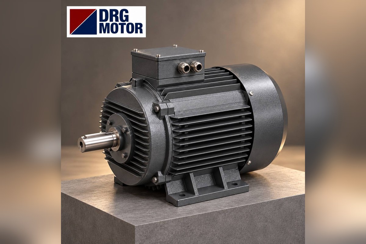

A B34 motor sits on its feet (B3) and can, at the same time, be bolted to the driven machine through a small face flange with tapped holes on its front end shield (B14, FT). To order the right B34 motor you need, besides power and speed, these dimensions: shaft height H, foot hole spacing A×B, shaft diameter and length D×E, small flange outer diameter P, pitch circle M and spigot diameter N. Foot and shaft dimensions depend on the IEC frame and can be checked in the table below; small flange dimensions are not tabulated in the DRG catalogue, so they must be measured on your existing motor and confirmed with us before ordering.
This distinction matters because more than one small flange size can be used on the same frame, and a motor with the wrong flange will simply not fit the gearbox or mating part. Before taking any measurement, isolate the motor at the panel, lock and tag the breaker, and leave cable removal and the terminal connection of the new motor to a qualified electrician. Measure only a de-energised, stationary motor.
What really sets the price is power, speed and frame. DRG Motor is an electric motor manufacturer, supplier and seller: you can see current prices for models of the same power and speed among the 120 models on Buy Electric Motors Online, and get the small-flange version confirmed by sending us your measurements.
What exactly is B34? B3, B5, B14, B34 and B35 side by side
IEC mounting codes tell you how the motor is held. B3 has feet only. B5 has a large flange: it overhangs the housing and the bolts pass through its holes (FF type). B14 has a small face flange: it stays within the housing diameter, its holes are tapped and the bolts screw into the motor from the other side (FT type). B34 and B35 are these two flanges combined with a foot-mounted housing.
| Code | Held by | Flange type | Typical use |
|---|---|---|---|
| B3 | Feet | None | Belt drive, coupled base |
| B5 | Large flange | FF, clearance holes | Gearbox, bell-housing pump |
| B14 | Small face flange | FT, tapped holes | Small gearbox, agitator |
| B34 | Feet + small flange | FT, tapped holes | Carried by feet, centred by flange |
| B35 | Feet + large flange | FF, clearance holes | Pump and gearbox sets |
A machine designer who chooses B34 usually wants two things: the feet carry the weight of the motor, while the shaft axis is located on the driven machine by the flange spigot. That is why replacing a B34 motor with a foot-only motor often introduces misalignment, and replacing it with a B14-only motor leaves the foot fixing unused. A general comparison is in our article on B3, B5, B14 and B35 mounting types; here we focus only on the moment of ordering.
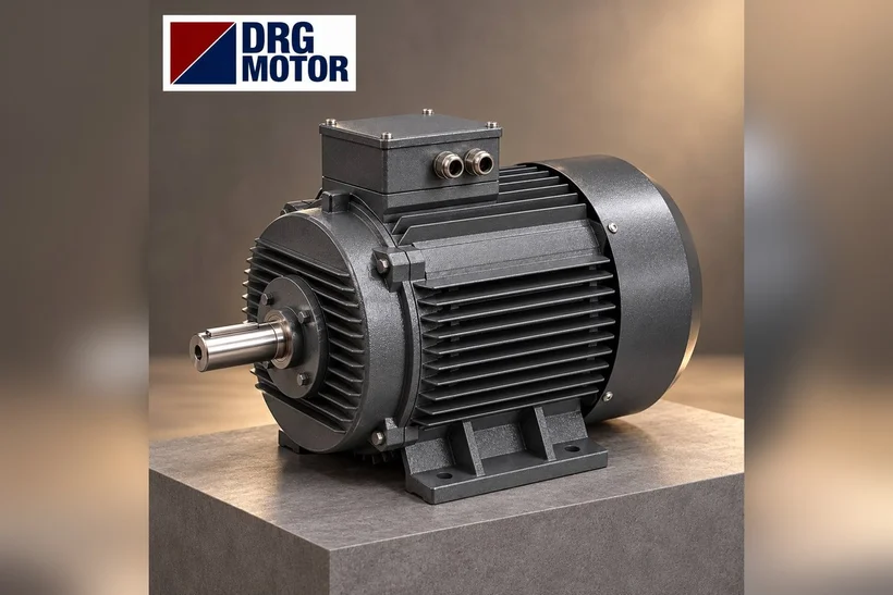
The 3 most common mistakes when ordering a B34 motor
1. Confusing B34 with B35
Both have feet and a flange, so they get described the same way over the phone. The quickest way to tell them apart is to look at the flange holes: if a bolt passes through and the flange overhangs the housing, it is B35 (FF); if the holes are blind and tapped and the flange stays within the housing diameter, it is B34 (FT). Large flange dimensions are listed frame by frame in the catalogue; small flange dimensions are not.
2. Guessing the small flange from the frame number
The frame number (e.g. 90L) fixes foot and shaft dimensions, not the small flange: different FT flange sizes can be used on the same frame. An order placed as “frame 90, standard flange” may not fit at installation. A B34 order should not be finalised before the flange outer diameter, pitch circle and spigot diameter have been measured.
3. Not measuring the shaft end
B34 motors usually go into a gearbox or a coupling. Shaft diameter D, length E and key width F are standard for each frame, but old or imported motors can differ. Measure the existing shaft diameter with a caliper and its length from the flange face to the shaft end, and note the width of the keyway.
Measurements to send with your order: checklist
Fill in this list next to the existing motor; adding a photo for each measurement speeds up confirmation.
- Power (kW) and rated speed: from the nameplate; without a plate the frame is found from the dimensions below.
- Shaft height H: from the foot base to the shaft centre.
- Foot hole spacing A (across the shaft) and B (along the shaft), foot hole diameter K.
- C: from the drive-end foot hole to the shaft shoulder.
- Shaft D×E and key width F.
- Small flange outer diameter P.
- Pitch circle M, number of tapped holes and thread size.
- Spigot (pilot) diameter N and spigot length T.
- Terminal box position (top, right, left seen from the shaft) and cable entry.
- Supply voltage and starting method (direct, star-delta, inverter).
Drawings with foot, shaft and large flange dimensions are on our technical drawings page, frame by frame; compare your measurements with them to identify your motor’s frame before ordering.
Click to see current electric motor prices and order nowSEE PRICES →
Foot and shaft dimensions by frame (DRG catalogue)
The foot and shaft dimensions of a B34 motor are the same as the B3 dimensions of that frame. Values are taken from the DRG catalogue (mm); small flange dimensions are intentionally not shown here.
| Frame | Feet A×B, hole K | H / C | Shaft D×E, key F |
|---|---|---|---|
| 63 | 100×80 mm, 4–Φ7 | 63 / 40 mm | 11×23 mm, 4 mm |
| 71 | 112×90 mm, 4–Φ7 | 71 / 45 mm | 14×30 mm, 5 mm |
| 80 | 125×100 mm, 4–Φ10 | 80 / 50 mm | 19×40 mm, 6 mm |
| 90S | 140×100 mm, 4–Φ10 | 90 / 56 mm | 24×50 mm, 8 mm |
| 90L | 140×125 mm, 4–Φ10 | 90 / 56 mm | 24×50 mm, 8 mm |
| 100L | 160×140 mm, 4–Φ12 | 100 / 63 mm | 28×60 mm, 8 mm |
| 112M | 190×140 mm, 4–Φ12 | 112 / 70 mm | 28×60 mm, 8 mm |
| 132S | 216×140 mm, 4–Φ12 | 132 / 89 mm | 38×80 mm, 10 mm |
| 132M | 216×178 mm, 4–Φ12 | 132 / 89 mm | 38×80 mm, 10 mm |
Example: if you measured foot hole spacing of 140 × 125 mm, a shaft height of 90 mm and a 24 × 50 mm shaft, your motor is a 90L frame. In the DRG catalogue this frame covers 1.5 kW 4-pole (DRG-90L-4), 2.2 kW 2-pole (DRG-90L-2) and 1.1 kW 6-pole (DRG-90L-6). Only dimension B separates 90S from 90L (100 and 125 mm); A, H and the shaft are the same. The same logic applies to 132S and 132M (B: 140 and 178 mm).
How to measure the small flange on your existing motor
Since our catalogue gives no figures for the small flange, the dimensions come from your motor. A caliper and a tape measure are enough:
- P – flange outer diameter: the outermost diameter of the flange face, across two opposite points.
- N – spigot diameter: the outer diameter of the thin ring (pilot) protruding from the flange face. This is the surface that locates on the mating part; measure it most carefully.
- M – pitch circle: the distance between the centres of two opposite tapped holes. If you can only reach two adjacent holes on a 4-hole flange, M = s × √2 ≈ s × 1.414 (s: centre distance of two adjacent holes).
- Thread size: try a bolt in the hole or use a thread gauge; note the hole depth.
- T – spigot length: from the flange face to the end of the pilot ring.
Send the values without rounding, each with a photo showing a ruler. The exact fit of the small flange is confirmed with these values before ordering; never order a flanged motor on an “approximate” measurement. For a general description of small-flange motors and B14-only builds, see our B14 flange motor ordering guide.
Which frame for which power? DRG model table for B34
The B34 arrangement is most common at low and medium power, on gearbox and agitator sets. The 4-pole aluminium-frame models below cover this range; currents are at 400 V.
| Model | Power / speed | Frame | Current 400 V |
|---|---|---|---|
| DRG-712-4 | 0.37 kW / 1340 rpm | 71 aluminium | 0.92 A |
| DRG-801-4 | 0.55 kW / 1400 rpm | 80 aluminium | 1.31 A |
| DRG-802-4 | 0.75 kW / 1420 rpm | 80 aluminium | 1.75 A |
| DRG-90S-4 | 1.1 kW / 1445 rpm | 90S aluminium | 2.48 A |
| DRG-90L-4 | 1.5 kW / 1445 rpm | 90L aluminium | 3.3 A |
| DRG-100L1-4 | 2.2 kW / 1450 rpm | 100L aluminium | 4.52 A |
| DRG-100L2-4 | 3 kW / 1450 rpm | 100L aluminium | 6.02 A |
| DRG-112M-4 | 4 kW / 1450 rpm | 112M aluminium | 7.95 A |
Up to 3 kW these models are rated 230/400 V and are star-connected on a 400 V supply; from 4 kW (DRG-112M-4) the rating is 400/690 V and they are delta-connected on 400 V. Keep this limit in mind if you plan star-delta starting. Currents for other powers and voltages are in the motor current chart. All values of the 1.5 kW model in the table:
- Model: DRG-90L-4
- Power: 1.5 kW
- Rated speed: 1445 rpm
- Frame: 90L aluminium
- Rated voltage: 230/400 V (Δ/Y)
- Connection at 400 V: Y (star)
- Current 400 V: 3.3 A
- cos φ: 0.77
- Rated torque: 9.91 Nm
B34, B35 or plain B3? Decision table
| Current situation | Choice | Reason |
|---|---|---|
| Feet + tapped small flange | B34 | Same spigot and feet |
| Feet + overhanging flange | B35 | Large flange is in catalogue |
| Motor hangs on flange only | B14 | Feet not needed |
| Belt drive, flange unused | B3 | No flange needed |
| Flange cannot be measured | Measure / drawing first | Never order on a guess |
Whenever you are unsure, the deciding factor is how the driven machine holds the motor: if the flange does the centring, keep the flange; if the flange only serves as a bolted fixing and the shaft is aligned through a coupling, a foot-mounted solution can also be considered. In that second case, the machine must not be run before the coupling alignment has been checked with a dial gauge.
DRG motors suited to B34 arrangements
- DRG-712-4 – 0.37 kW – 1340 rpm – 71 aluminium
- DRG-802-4 – 0.75 kW – 1420 rpm – 80 aluminium
- DRG-90L-4 – 1.5 kW – 1445 rpm – 90L aluminium
- DRG-100L2-4 – 3 kW – 1450 rpm – 100L aluminium
- DRG-112M-4 – 4 kW – 1450 rpm – 112M aluminium
- DRG-90S-2 – 1.5 kW – 2895 rpm – 90S aluminium
Click to see current prices and order these motors nowSEE PRICES →
Frequently Asked Questions
What does B34 motor mean?
B34 is a mounting arrangement in which a foot-mounted (B3) housing also carries a small face flange with tapped holes (B14, FT) on its front end shield. The motor sits on its feet and is aligned to the driven machine by the flange spigot.
What is the difference between B34 and B35 motors?
Both have feet and a flange. On B35 the large flange overhangs the housing and has clearance holes (FF); on B34 the small flange stays within the housing diameter and has tapped holes (FT). One cannot be fitted directly in place of the other.
Is the B34 flange size standard for each frame?
Foot and shaft dimensions are standard per frame; for the small flange, different sizes can be used on the same frame. P, M and N must therefore be measured on the existing motor and confirmed before ordering.
What power is a frame 90 B34 motor?
In the DRG catalogue, frame 90S covers 0.75 kW 6-pole, 1.1 kW 4-pole and 1.5 kW 2-pole; frame 90L covers 1.1 kW 6-pole, 1.5 kW 4-pole and 2.2 kW 2-pole. The cast iron compact series also has a 3 kW 2-pole model in frame 90L (DRG-90L-2K).
Send your measurements, a nameplate photo or your question to +90 (542) 666 11 11 or [email protected]; all channels are listed on our contact page. For current prices of all models, visit Buy Electric Motors Online.