 English
 Le français
 Türkçe

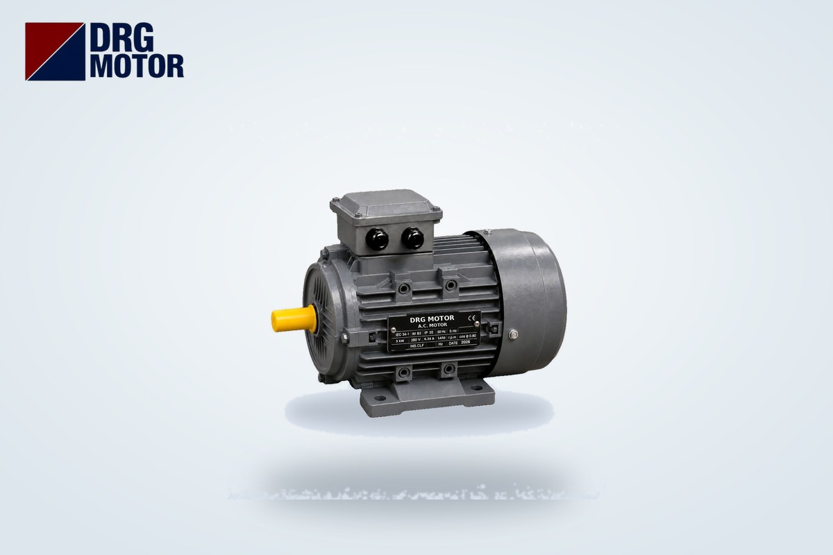

Selecting a motor and gearbox takes four steps: first define the output speed and output torque the machine needs, then divide the motor's rated speed by that output speed to get the ratio (i = nmotor / nout), next check the output torque with M2 ≈ 9550 · P / nout · ηgear, and finally make sure the gearbox rating is not lower than the load torque multiplied by the service factor from the gearbox catalogue. For example, a 3 kW motor with a rated speed of 1450 rpm gives about 58 rpm through a 25:1 gearbox; with a gearbox efficiency of 0.95 the output torque is about 469 Nm.
Selection often starts at the wrong end: the motor power is chosen first and a gearbox that "fits" is found afterwards. The right way is to work backwards from the load. Output speed sets the machine speed, output torque tells you whether the load can be driven, the service factor tells you whether the gearbox will withstand shocks and daily operating hours, and the flange and shaft dimensions decide whether the two can physically be joined. On the motor side you can filter the 120 models on our Buy Electric Motors Online page by kW, speed and frame; the examples in this article are calculated with the catalogue data of these models.
We explained why the motor and gearbox must be considered together in Why Is Motor–Gearbox Compatibility Important?; here we focus directly on the calculation.
Five pieces of information you need before you start
Before opening a gearbox catalogue, collect this information from the machine side:
- Output speed (n2): If the belt speed is known, it is calculated from the drum diameter with n2 = 60 · v / (π · D).
- Load torque (Mload): The torque required at the output shaft. For a belt: pull force × drum radius.
- Load character: Uniform (belt, pump), moderate shock (mixer, feeder) or heavy shock (crusher, presses)? The service factor is read accordingly.
- Daily operating hours and starts per hour: The service factor table is read with these two values.
- Mounting: Will the motor be connected to the gearbox with a B5 flange, or as a foot-mounted motor with a coupling? Is the gearbox foot-mounted, flange-mounted or hollow-shaft?
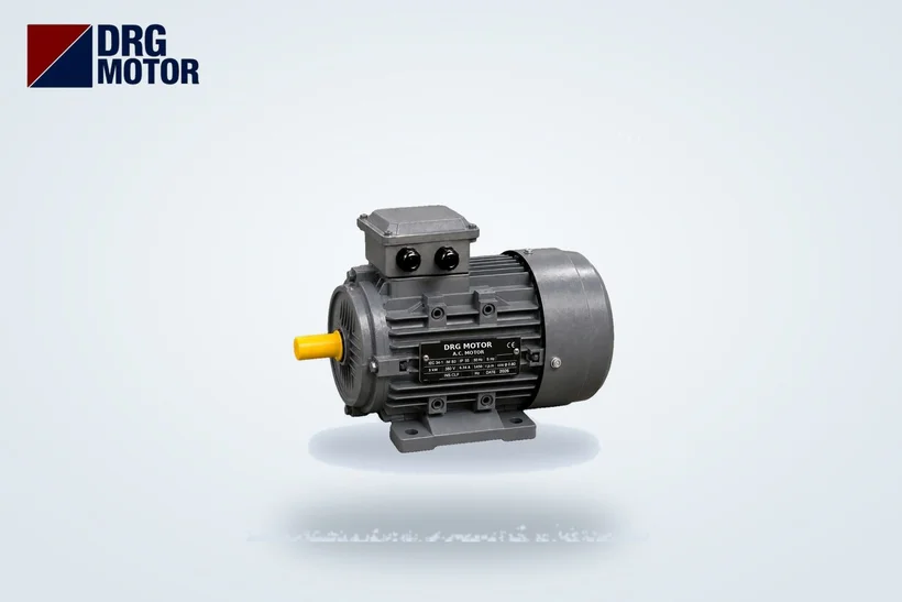
Step 1: Calculate the gear ratio with the motor's rated speed
Use the rated speed on the nameplate, not the synchronous speed (1500, 1000, 3000 rpm). An induction motor runs slightly below synchronous speed under load because of slip; using 1450 or 1460 instead of 1500 gives the correct output speed from the start.
The formula is simple: i = nmotor / n2. The calculated ratio rarely exists exactly in the catalogue; choose the nearest standard ratio and recalculate the actual output speed: n2 = nmotor / iselected.
The same output speed can also be reached with motors of different pole numbers. The table below shows the ratios needed for 50 rpm output with three 3 kW motors:
| Model | Power | Rated speed | Rated torque | Ratio for 50 rpm |
|---|---|---|---|---|
| DRG-100L-2 | 3 kW | 2895 rpm | 9.9 Nm | 57.9 |
| DRG-100L2-4 | 3 kW | 1450 rpm | 19.8 Nm | 29 |
| DRG-132S-6 | 3 kW | 968 rpm | 29.6 Nm | 19.4 |
A high ratio means more gear stages or a worm-type gearbox. A low-speed (6-pole) motor reduces the ratio but the motor itself moves up to a larger frame: at 3 kW the 2-pole motor is in a 100L frame while the 6-pole motor is in a 132S frame. For applications such as conveyors and mixers, a 4-pole motor is a balanced starting point.
Step 2: Check the output torque with the gearbox efficiency
A gearbox reduces speed and increases torque roughly by the ratio; the loss in between is expressed by the gearbox efficiency (ηgear). Output torque:
M2 ≈ 9550 · P / n2 · ηgear (P in kW, n2 in rpm, M2 in Nm)
The same result can be reached from the motor's rated torque: M2 ≈ Mmotor · i · ηgear. Always take ηgear from the catalogue of the gearbox you select; it is high for helical and bevel gearboxes and noticeably lower for worm gearboxes, depending on the ratio.
The M2 you find must be above the load torque. If it is below, either increase the motor power or accept a lower output speed with a larger ratio.
Step 3: Apply the service factor according to the load type
The service factor (fs or fB) is the multiplier that shows how much "margin" the gearbox's catalogue rated torque needs in your application. The same torque runs a gearbox comfortably on a uniform belt, but wears out the gears quickly on a shock-loaded crusher. The rule is:
M2,catalogue ≥ Mload · fs
The fs value is read from the service factor table in each gearbox manufacturer's catalogue, whose rows and columns cover load character (uniform / moderate shock / heavy shock), daily operating hours and starts per hour. Take this value from the table of the gearbox you will actually use, not from a generic list.
The motor service factor is a different concept: it describes how far a motor can be loaded above its nameplate power; see What Does Service Factor Mean in an Electric Motor? for details. The two should not be confused.
Why does starting torque matter for the service factor?
An induction motor delivers a multiple of its rated torque at start-up. For example, for DRG-132M-4 (7.5 kW, 1460 rpm) the catalogue starting torque ratio is Ts/Tn = 2.0; with direct-on-line starting, twice the rated torque briefly reaches the gearbox input and is multiplied by the ratio at the output. Compare this peak with the short-time permissible torque in the gearbox catalogue; with heavy starting, a soft starter or drive reduces the shock.
Step 4: Motor flange and shaft must match the gearbox input
Even if the calculation works, the motor must physically fit the gearbox. In direct-coupled (motor-flange) gearboxes the input adapter is machined for a specific IEC frame size; the motor's shaft diameter (D), shaft length (E), key width (F) and the B5 flange's bolt circle (M), spigot diameter (N) and outer diameter (P) must match this adapter.
| Model | Power / rated speed | Frame | Shaft D × E (mm) | Key F (mm) | B5 flange M / N / P (mm) | Flange hole S (mm) |
|---|---|---|---|---|---|---|
| DRG-90L-4 | 1.5 kW / 1445 rpm | 90L | 24 × 50 | 8 | 165 / 130 / 200 | 12 |
| DRG-100L2-4 | 3 kW / 1450 rpm | 100L | 28 × 60 | 8 | 215 / 180 / 250 | 14.5 |
| DRG-112M-4 | 4 kW / 1450 rpm | 112M | 28 × 60 | 8 | 215 / 180 / 250 | 14.5 |
| DRG-132S-4 | 5.5 kW / 1460 rpm | 132S | 38 × 80 | 10 | 265 / 230 / 300 | 14.5 |
| DRG-132M-4 | 7.5 kW / 1460 rpm | 132M | 38 × 80 | 10 | 265 / 230 / 300 | 14.5 |
| DRG-160M-6 | 7.5 kW / 970 rpm | 160M | 42 × 110 | 12 | 300 / 250 / 350 | 18.5 |
| DRG-160M-4 | 11 kW / 1465 rpm | 160M | 42 × 110 | 12 | 300 / 250 / 350 | 18.5 |
The 100L and 112M frames share the same shaft size and flange diameters (M / N / P); increasing power between them may not require a new adapter. Moving from 112M to 132S, the shaft grows from 28 to 38 mm and the flange outer diameter from 250 to 300 mm. For the differences between B5 and B14 connections, see How to Choose a Flange Motor for a Gearbox.
Worked examples: conveyor and mixer
Example 1: Belt conveyor
Belt speed 0.9 m/s, drive drum diameter 300 mm, required belt pull 2500 N.
- Drum speed: n2 = 60 · 0.9 / (π · 0.3) ≈ 57.3 rpm
- Load torque: Mload = 2500 N × 0.15 m = 375 Nm
- Power at the drum: 375 × 57.3 / 9550 ≈ 2.25 kW; with a gearbox efficiency of 0.95, ≈ 2.37 kW is needed at the motor shaft → 3 kW motor.
- Motor: DRG-100L2-4, 1450 rpm. Ratio: 1450 / 57.3 ≈ 25.3 → a 25:1 ratio is chosen from the catalogue.
- Actual output speed: 1450 / 25 = 58 rpm; belt speed ≈ 0.91 m/s.
- Output torque: 9550 × 3 / 58 × 0.95 ≈ 469 Nm ≥ 375 Nm, suitable.
- Gearbox: catalogue rated torque at least 375 × fs; fs is read from the gearbox table for uniform load and your daily operating hours.
- Connection: 100L frame, shaft 28 × 60 mm, B5 flange 215 / 180 / 250 mm.
If the loaded belt stops and starts frequently, upsizing to 4 kW (DRG-112M-4) can be considered; since shaft and flange stay the same, the same gearbox input can be used. For the full belt calculation, see Conveyor Belt Motor Selection.
Example 2: Mixer
The mixer shaft must turn at 30 rpm and the designer requires 2000 Nm at the shaft.
- Power at the shaft: 2000 × 30 / 9550 ≈ 6.28 kW; with ηgear = 0.95, ≈ 6.61 kW at the motor → 7.5 kW motor.
- Option A: DRG-132M-4, 1460 rpm → i = 1460 / 30 ≈ 48.7
- Option B: DRG-160M-6, 970 rpm → i = 970 / 30 ≈ 32.3
- Output torque for both options: 9550 × 7.5 / 30 × 0.95 ≈ 2268 Nm ≥ 2000 Nm.
- Service factor: a mixer is usually treated as a moderate-shock load; the gearbox rated output torque must be at least 2000 Nm × fs. Read fs from the gearbox catalogue table for moderate shock and your daily operating hours.
- Starting: Ts/Tn = 2.0 for both motors; when starting with a full vessel, roughly twice the rated torque can briefly reach the output.
Option B may allow a gearbox with fewer stages thanks to the lower ratio, but the motor moves up to a 160M frame (shaft 42 × 110 mm); in A the motor is in a 132M frame (shaft 38 × 80 mm) with a higher ratio. The decision depends on the options in the gearbox catalogue.
Common selection mistakes
- Calculating the ratio with synchronous speed (1500 rpm); output speed ends up lower than expected.
- Assuming a worm gearbox has the same efficiency as a helical one.
- Confusing the gearbox service factor with the value on the motor nameplate, or not applying it at all.
- Choosing a motor two sizes larger "just in case" without checking the gearbox against peak torque.
- Forgetting that shaft diameter and flange size change with the frame (e.g. 112M → 132S).
Selection checklist
- Were output speed and load torque calculated from machine data?
- Was the ratio found with the motor's rated speed and the output speed recalculated with the nearest catalogue ratio?
- Is M2 ≈ 9550 · P / n2 · ηgear above the load torque?
- Is the gearbox rated torque ≥ Mload × fs? Was fs read from the gearbox's own table?
- Is the starting peak torque below the gearbox's short-time permissible torque?
- Do motor shaft D × E, key F and B5 flange M / N / P match the gearbox input?
- Were radial and axial loads on the output shaft checked?
For motor power and current calculations you can use our electric motor calculators.
Motors for gearbox applications
- DRG-90L-4 – 1.5 kW – 1500 rpm – 90L cast iron
- DRG-100L2-4 – 3 kW – 1500 rpm – 100L cast iron
- DRG-112M-4 – 4 kW – 1500 rpm – 112M cast iron
- DRG-132M-4 – 7.5 kW – 1500 rpm – 132M cast iron
- DRG-160M-6 – 7.5 kW – 1000 rpm – 160M cast iron
- DRG-160M-4 – 11 kW – 1500 rpm – 160M cast iron
Click to see current prices and order these motors nowSEE PRICES →
Frequently Asked Questions
How do you calculate a gearbox ratio?
Divide the motor's nameplate rated speed by the required output speed: i = nmotor / n2. For example, with a 1450 rpm motor and 58 rpm output the ratio is 25. Choose the nearest catalogue ratio and recalculate the output speed.
How do you find gearbox output torque?
With M2 ≈ 9550 · P / n2 · ηgear. With a 3 kW motor, 58 rpm output and a gearbox efficiency of 0.95, the output torque is about 469 Nm. Take the efficiency from the catalogue of the gearbox you select.
What service factor should a gearbox have?
There is no single number. It is read from the service factor table in the gearbox catalogue according to load type (uniform, moderate shock, heavy shock), daily operating hours and starts per hour; the gearbox rated torque must not be below load torque × fs.
Should I choose a 4-pole or 6-pole motor for a gearbox?
At the same power, a 6-pole motor reduces the ratio but needs a larger frame: at 7.5 kW, DRG-132M-4 is in a 132M frame and DRG-160M-6 in a 160M frame. Decide by considering gearbox size, available ratios and installation space together.
If you want to check motor power, speed and flange size together for your gearbox application, contact us at +90 (542) 666 11 11 or [email protected], or use our contact page. You can browse all models on our Buy Electric Motors Online page.