 English
 Le français
 Türkçe

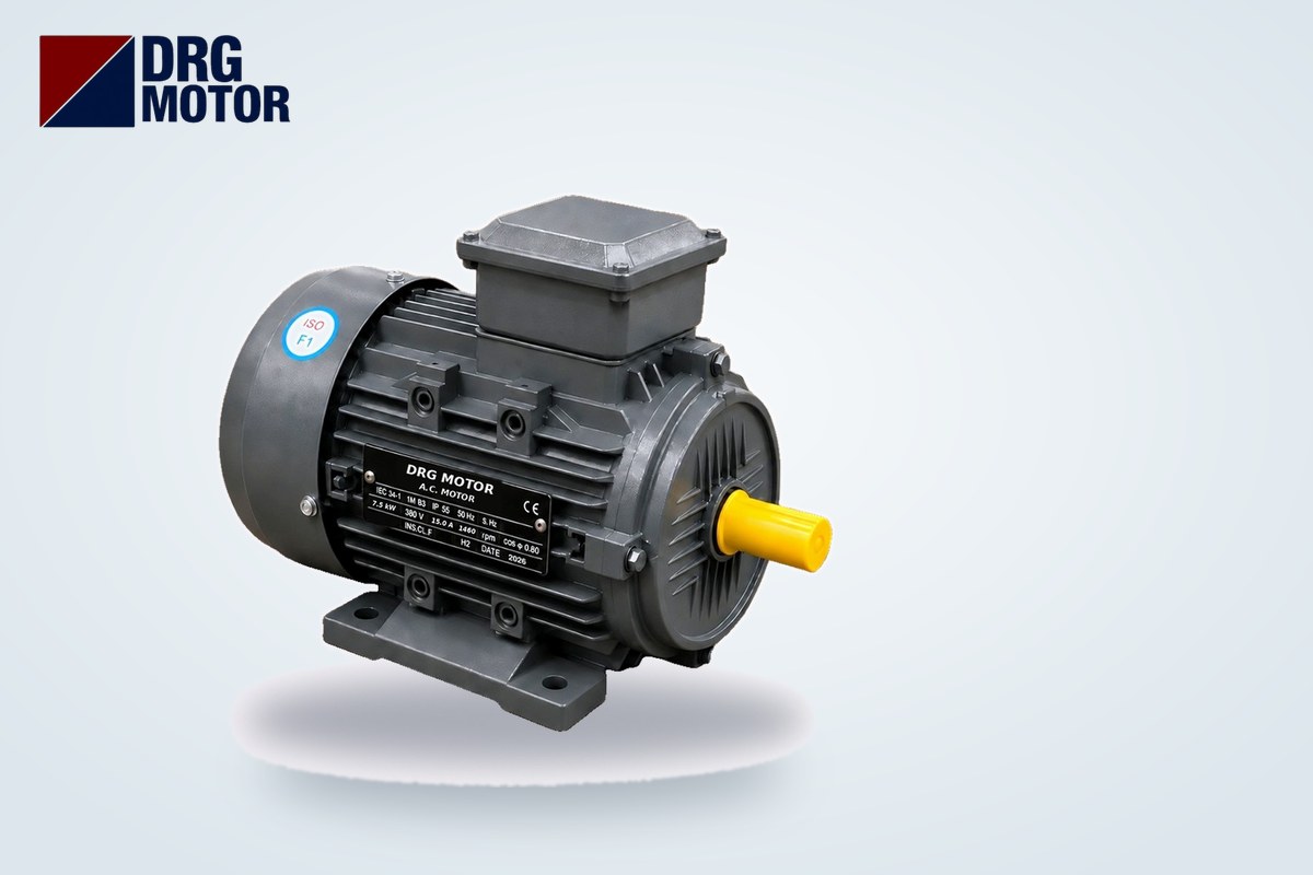

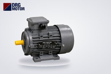
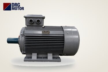
Four dimensions decide whether a B3 foot-mounted motor fits its base: H (height from the foot face to the shaft centre), A (distance between the foot holes on either side of the shaft), B (distance between the foot holes along the shaft) and K (foot hole diameter). Example: on a 132M frame H = 132 mm, A = 216 mm, B = 178 mm, K = 4–Φ12. The number in the frame size is H itself; the letter (S, M, L) indicates a different B distance at the same height.
When replacing an old motor, if H and A × B match, the new one bolts onto the existing base; if not, the coupling alignment is lost or new holes are needed in the base. The table below lists the catalogue dimensions frame by frame for the 120 models in our online shop. We do not repeat the differences between mounting types here; for that, see our articles B3, B5, B14 and B35 mounting types compared and flange or foot mounted?.
B3 motor dimensions table: frames 63 to 355 (mm)
All values are in millimetres. Where the 2-pole motor of a frame has a different shaft diameter and length, it is given on a separate row. Aluminium and cast iron frames of the same IEC size have the same dimensions in the catalogue. "4–Φ12" in column K means four holes of 12 mm diameter.
| Frame | A | B | C | H | K | AC | AD | L | D × E (shaft) |
|---|---|---|---|---|---|---|---|---|---|
| 63 | 100 | 80 | 40 | 63 | 4–Φ7 | 120 | 113 | 217 | 11 × 23 |
| 71 | 112 | 90 | 45 | 71 | 4–Φ7 | 136 | 119 | 242 | 14 × 30 |
| 80 | 125 | 100 | 50 | 80 | 4–Φ10 | 167 | 147 | 304 | 19 × 40 |
| 90S | 140 | 100 | 56 | 90 | 4–Φ10 | 182.4 | 154.5 | 336 | 24 × 50 |
| 90L | 140 | 125 | 56 | 90 | 4–Φ10 | 182.4 | 154.5 | 361 | 24 × 50 |
| 100L | 160 | 140 | 63 | 100 | 4–Φ12 | 205.4 | 166 | 406 | 28 × 60 |
| 112M | 190 | 140 | 70 | 112 | 4–Φ12 | 230 | 188 | 394 | 28 × 60 |
| 132S | 216 | 140 | 89 | 132 | 4–Φ12 | 258.4 | 203 | 438 | 38 × 80 |
| 132M | 216 | 178 | 89 | 132 | 4–Φ12 | 258.4 | 203 | 476 | 38 × 80 |
| 160M | 254 | 210 | 108 | 160 | 4–Φ14.5 | 314 | 251 | 608 | 42 × 110 |
| 160L | 254 | 254 | 108 | 160 | 4–Φ14.5 | 314 | 251 | 652 | 42 × 110 |
| 180M | 279 | 241 | 121 | 180 | 4–Φ14.5 | 355 | 267 | 688 | 48 × 110 |
| 180L | 279 | 279 | 121 | 180 | 4–Φ14.5 | 355 | 267 | 726 | 48 × 110 |
| 200L | 318 | 305 | 133 | 200 | 4–Φ18.5 | 397 | 299 | 779 | 55 × 110 |
| 225S | 356 | 286 | 149 | 225 | 4–Φ18.5 | 446 | 322 | 824 | 60 × 140 |
| 225M (4/6 pole) | 356 | 311 | 149 | 225 | 4–Φ18.5 | 446 | 322 | 849 | 60 × 140 |
| 225M (2 pole) | 356 | 311 | 149 | 225 | 4–Φ18.5 | 446 | 322 | 819 | 55 × 110 |
| 250M (4/6 pole) | 406 | 349 | 168 | 250 | 4–Φ24 | 485 | 358 | 910 | 65 × 140 |
| 250M (2 pole) | 406 | 349 | 168 | 250 | 4–Φ24 | 485 | 358 | 910 | 60 × 140 |
| 280S (4/6 pole) | 457 | 368 | 190 | 280 | 4–Φ24 | 547 | 387 | 982 | 75 × 140 |
| 280S (2 pole) | 457 | 368 | 190 | 280 | 4–Φ24 | 547 | 387 | 982 | 65 × 140 |
| 280M (4/6 pole) | 457 | 419 | 190 | 280 | 4–Φ24 | 547 | 387 | 1033 | 75 × 140 |
| 280M (2 pole) | 457 | 419 | 190 | 280 | 4–Φ24 | 547 | 387 | 1033 | 65 × 140 |
| 315S (4/6 pole) | 508 | 406 | 216 | 315 | 4–Φ28 | 620 | 527 | 1224 | 85 × 170 |
| 315S (2 pole) | 508 | 406 | 216 | 315 | 4–Φ28 | 620 | 527 | 1194 | 65 × 140 |
| 315M (4/6 pole) | 508 | 457 | 216 | 315 | 4–Φ28 | 620 | 527 | 1334 | 85 × 170 |
| 315M (2 pole) | 508 | 457 | 216 | 315 | 4–Φ28 | 620 | 527 | 1304 | 65 × 140 |
| 315L (4/6 pole) | 508 | 508 | 216 | 315 | 4–Φ28 | 620 | 527 | 1334 | 85 × 170 |
| 315L (2 pole) | 508 | 508 | 216 | 315 | 4–Φ28 | 620 | 527 | 1304 | 65 × 140 |
| 355M (4/6 pole) | 610 | 560 | 254 | 355 | 6–Φ28 | 698 | 642 | 1516 | 100 × 170 |
| 355M (2 pole) | 610 | 560 | 254 | 355 | 6–Φ28 | 698 | 642 | 1486 | 75 × 140 |
| 355L (4/6 pole) | 610 | 630 | 254 | 355 | 6–Φ28 | 698 | 642 | 1516 | 100 × 170 |
| 355L (2 pole) | 610 | 630 | 254 | 355 | 6–Φ28 | 698 | 642 | 1486 | 75 × 140 |
Frames 400M, 400L are not included because the catalogue does not give foot dimensions for them; confirm the dimensions separately before ordering.
What the letters mean: A, B, C, H, K, AC, AD, L
- A – Centre distance between the foot holes to the right and left of the shaft (across the shaft).
- B – Centre distance between the front and rear foot holes on the same side (along the shaft).
- C – Distance from the shaft shoulder to the centre of the nearest foot hole.
- H – Height from the foot mounting face to the shaft axis; identical to the frame number.
- K – Foot hole diameter and number of holes.
- AC – Outside diameter of the frame (including cooling fins); for side wall and guard clearance.
- AD – Terminal box height dimension; to check whether the box clashes with a cover, cable duct or machine part.
- L – Overall length from the shaft end to the back of the fan cover.
- D × E – Shaft diameter × shaft length (for coupling or pulley selection).
Same H, different B: what do the letters S, M and L change?
The frame letter only changes the B distance along the shaft (and the overall length L with it); H, A and K stay the same. The pairs most often confused on site:
- 90S – 90L: A = 140 mm on both; B 100 → 125 mm, L 336 → 361 mm.
- 132S – 132M: A = 216 mm; B 140 → 178 mm, L 438 → 476 mm.
- 160M – 160L: A = 254 mm; B 210 → 254 mm, L 608 → 652 mm.
So when a 132M motor arrives instead of a 132S, the rear foot holes sit 38 mm further back. A second pair of rear holes can then be drilled in the base relative to the existing front holes; because the shaft height and the front hole position do not change, coupling alignment is kept. In the opposite case (from a long frame to a short one) the rear holes again have to be moved forward.
How to measure foot dimensions on site
On a motor whose nameplate is missing or whose frame size cannot be read, the dimensions can be taken with a tape measure and a caliper:
- A and B: Instead of measuring edge to edge and adding the hole diameter, measure between the same edges of two opposite holes (left edge to left edge); this gives the centre-to-centre distance directly.
- K: Measure the hole diameter with a caliper. If the hole is slotted (for belt tensioning), note the narrowest dimension.
- H: Stand the motor on a flat surface, measure the height of the top of the shaft and subtract half the shaft diameter. For frame 132 with a 38 mm shaft the measured value should be ≈151 mm: 151 − 38/2 = 132 mm.
- Diagonal check: The distance between two diagonally opposite holes should be √(A² + B²). For 132M √(216² + 178²) ≈ 279.9 mm, for 132S ≈257.4 mm. This one measurement tells S from M.
- C and shaft end: The distance from the nearest foot hole centre to the shaft end is C + E. On frame 132 it is 89 + 80 = 169 mm, on 100L 63 + 60 = 123 mm. This value tells you where the coupling or pulley will sit on the new motor.
Once your measured H, A and B match a row in the table, the frame size is known. The motor power and speed are then chosen from the nameplate or from the duty.
Checking H and A × B when replacing an old motor
The most time-wasting mistake in a replacement is taking a motor with the right power but a different frame to site. Check in this order:
- Is H the same? If not, the axis shifts on a coupled drive; shims under the feet are only a temporary fix for small differences, the permanent fix is the right frame.
- Is A the same? A difference in A means new holes in the base; since A changes with frame height, it usually also signals a difference in H.
- Is B the same? If it is an S/M/L difference, it is solved by adding a pair of rear holes.
- Is K the same? The existing bolt must pass through the new hole and seat fully with its washer.
- D × E and C: The shaft diameter must suit the coupling hub, and the C + E distance the coupling gap.
- AC, AD and L: The new motor must fit the guard, the side wall and the cable duct on the terminal side.
Motors of the same power do not always share a frame: for example, at 5.5 kW 4-pole the standard model uses frame 132S while the compact DRG-112M-4K uses frame 112M. If you choose the compact motor, H (112 mm) and A × B (190 × 140 mm) change too; prepare the base accordingly.
Points to watch when drilling a base or baseframe
- Mark the holes from the A and B values in the table with a steel rule and square rather than using the motor itself as a template; compare the diagonals.
- On belt drives, slotting the holes perpendicular to the shaft lets the motor slide for belt tensioning.
- On coupled drives, drill the two front holes first, fix the motor loosely, align it, then mark the rear holes.
- Check with feeler gauges that all four feet sit flat (soft foot); a foot that does not seat distorts the frame when tightened and causes vibration.
- Check the flatness of the base, the side clearance against the AC dimension and the space behind the fan cover for air intake.
If the connection is by flange, the flange dimensions decide instead of the foot dimensions; see our B5 motor flange dimensions table article. For power and current calculations, use the electric motor calculators page.
Motors in these frames
Example models from each frame range (the product page includes the dimension drawing and all dimensions):
- DRG-711-4 – 0.25 kW – 1500 rpm – 71 frame, aluminium
- DRG-90L-4 – 1.5 kW – 1500 rpm – 90L frame, cast iron
- DRG-112M-4 – 4 kW – 1500 rpm – 112M frame, cast iron
- DRG-132M-4 – 7.5 kW – 1500 rpm – 132M frame, cast iron
- DRG-160L-4 – 15 kW – 1500 rpm – 160L frame, cast iron
- DRG-180M-4 – 18.5 kW – 1500 rpm – 180M frame, cast iron
Click to see current prices and order these motors nowSEE PRICES →
Frequently Asked Questions
How do you read motor foot dimensions?
A is the distance between the foot holes on either side of the shaft, B between the holes along the shaft, H the height from the foot face to the shaft axis and K the hole diameter. For example, on frame 100L A × B = 160 × 140 mm, H = 100 mm, K = 4–Φ12.
What does the motor frame number indicate?
The number is the shaft height (H) in millimetres: on frame 112M H = 112 mm. The letter indicates the foot length at the same height; on 132S B = 140 mm, on 132M B = 178 mm.
Do 90S and 90L motors have the same foot dimensions?
H = 90 mm, A = 140 mm and K are the same; B is 100 mm on 90S and 125 mm on 90L. Overall length also rises from 336 mm to 361 mm.
How is the shaft height of a B3 motor measured?
Stand the motor on a flat floor, measure the height of the top of the shaft and subtract half the shaft diameter. On frame 132 with a 38 mm shaft you measure ≈151 mm, giving H = 132 mm.
Send us the nameplate or the dimensions of your old motor and we will find the match together: phone +90 (542) 666 11 11, e-mail [email protected], contact page drgmotor.com/en/contact. You can review every model on the Buy Electric Motors Online page.