 English
 Le français
 Türkçe

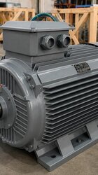
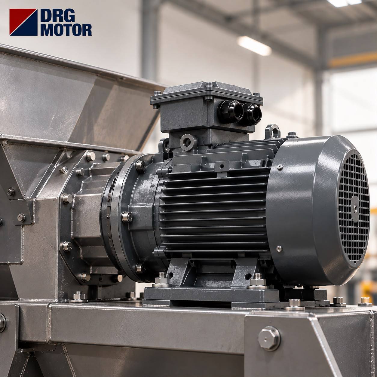

The fitting crew opens the input cover of the gearbox, brings the new motor up to it, and the shaft will not go into the bore. The flange outer diameter matches and all four holes line up, yet the gearbox input bushing is 24 mm while the motor shaft is 19 mm. The order form only said "0.75 kW, 4-pole, B5"; neither the frame size nor the shaft dimension had been written down. Because frame 80 and frame 90 motors carry the same FF165 flange, everything looked correct from the outside. In this article we go step by step through how to read the input side of a gearbox when choosing a flange motor for it, which dimensions define B5 and B14 connections, how to match frame and flange from the catalogue table, and what note should go on the order.
Reading the Input Side of the Gearbox
Motor selection has to start from the gearbox itself, because the side that defines the connection is the gearbox, not the motor. On a gearbox with an IEC input adapter, the nameplate or catalogue usually states the input as "IEC 90 B5", "FF165" or "24×50". That expression tells you three things: which motor frame it was machined for, the hole type of the flange and the diameter of the shaft bushing.
If the nameplate is worn or the adapter has been replaced, work from measurements. Take four values with a caliper: the outer diameter of the input flange, the distance between the centres of two opposite bolt holes (this gives the pitch circle diameter M), the inner diameter of the spigot recess and the inner diameter of the shaft bushing. Note the width of the keyway in the bushing as well. Compared with the table below, these four or five measurements largely settle which motor frame will fit. Keep the unit in mm and do not round; the difference between 165 and 160 is exactly the difference that produces a wrong order.
B5 and B14: The Difference Starts at the Gearbox Cover
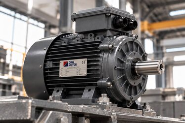
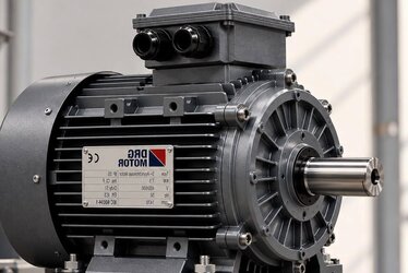
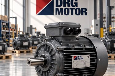
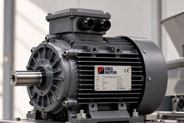
In B5 mounting the motor front end shield ends in a large flange whose holes are clearance holes (FF). The bolt passes through the hole and is fastened to the gearbox housing or to a nut on the other side. The flange outer diameter is larger than the frame, so the gearbox input must offer enough face to receive it.
In B14 mounting the flange is smaller and the holes are tapped (FT). The bolt comes from the gearbox side and screws directly into the motor flange. This is a compact solution, common on small and medium frame motors and on gearboxes with tight layouts. B14 flanges themselves come in small and large sizes, so a B14 order must state the flange size separately. For a detailed comparison of the hole types, see our article on the FF and FT hole difference on B5 and B14 flanges; the real question here is which one the gearbox cover was machined for. If the cover has plain clearance holes and a wide face, expect B5; if it has bolt seats that reach through to the motor flange, expect B14.
Foot-mounted gearbox applications may also call for B35 (feet + large flange) or B34 (feet + small flange). If the motor is fixed both by flange and by feet, the base height must be checked separately so that both connections stay on the same axis. If the gearbox works in a vertical position, for example on a mixer with the shaft facing down, state on the order whether the motor must suit a vertical mounting variant such as V1 or V3. In a vertical position oil, dust and condensation collect at different points, so the orientation of the terminal box and cable entry matters more than in horizontal mounting. Where the fan cover ends up on top, it should also be assessed on site whether a protective canopy is needed against rain or wash water.
Spigot Diameter: This Dimension Does the Alignment
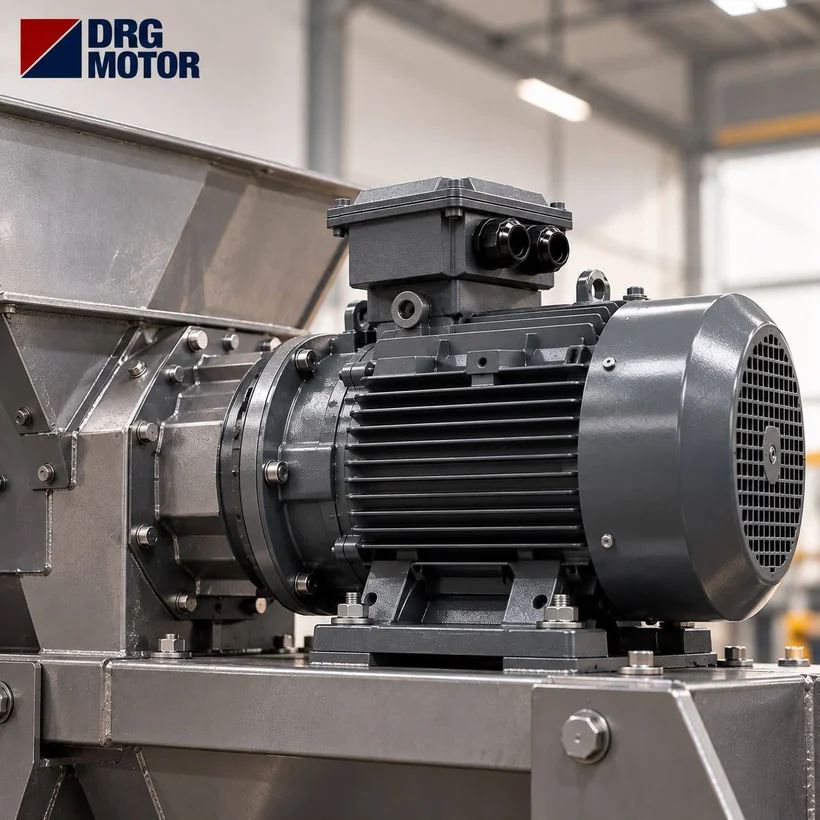
The raised ring in the centre of the flange (spigot, N) fits into the recess in the gearbox cover and aligns the motor shaft axially with the gearbox bushing. The bolts only clamp; the alignment comes from this close-tolerance fit. So even when the flange outer diameter and pitch circle match, a different spigot diameter means the motor will not seat, or will seat with play. A motor seated with play produces wear in the bushing, crushing in the keyway and vibration in the bearings over time.
The T value in the catalogue is the height of the spigot. If the gearbox recess is shallower than this height, the motor flange will not sit flat against the cover. As the DRG Motor catalogue also notes, in flange mounting the run-out of the mating face and the spigot shoulder should be checked before commissioning. In practice this means cleaning paint, burrs and rust from both faces, sliding the motor in straight without tilting, and tightening the bolts in a cross pattern.
Shaft D×E and Key: The Same Flange, a Different Shaft
The example in the introduction is not a coincidence. In the IEC system some neighbouring frames share the same flange but have different shaft diameters. Conversely, some frames share both flange and shaft completely. According to the catalogue table, the notable cases are:
- Frames 80 and 90: both FF165; shafts 19×40 and 24×50. The flange fits, the shaft does not.
- 100L and 112M: both FF215 with a 28×60 shaft. Either frame can be connected to the same gearbox input, which is useful when increasing power.
- Frames 160 and 180: both FF300; shafts 42×110 and 48×110.
- 225M: shaft 55×110 on the 2-pole version, 60×140 on the 4- and 6-pole versions. On the same frame, the number of poles changes the shaft.
Key width (F) and shaft height over key (GA) must also match the keyway in the bushing exactly. A key longer than the bushing depth is an easily missed detail that stops the motor from seating against the flange. Forcing the shaft into a tight bushing or filling an oversized bushing with shim sheet is a temporary fix that shortens the life of the bushing.
Frame-to-Flange Matching Table (B5 Dimensions)
The values below are taken from the IM B5 dimension table in the DRG Motor product catalogue; all dimensions are in mm. The flange name is given as FF plus the pitch circle diameter. B14 (FT) dimensions vary with flange size and are therefore not included; if you are ordering B14, ask for a dimensioned drawing.
| Frame | Poles | Shaft D×E | Key F | GA | Flange | M (pitch circle) | N (spigot) | P (outer dia.) | S (hole) | T |
|---|---|---|---|---|---|---|---|---|---|---|
| 63 | — | 11×23 | 4 | 12.5 | FF115 | 115 | 95 | 140 | 10 | 3 |
| 71 | — | 14×30 | 5 | 16 | FF130 | 130 | 110 | 160 | 10 | 3.5 |
| 80 | — | 19×40 | 6 | 21.5 | FF165 | 165 | 130 | 200 | 12 | 3.5 |
| 90S / 90L | — | 24×50 | 8 | 27 | FF165 | 165 | 130 | 200 | 12 | 3.5 |
| 100L | — | 28×60 | 8 | 31 | FF215 | 215 | 180 | 250 | 14.5 | 4 |
| 112M | — | 28×60 | 8 | 31 | FF215 | 215 | 180 | 250 | 14.5 | 4 |
| 132S / 132M | — | 38×80 | 10 | 41 | FF265 | 265 | 230 | 300 | 14.5 | 4 |
| 160M / 160L | — | 42×110 | 12 | 45 | FF300 | 300 | 250 | 350 | 18.5 | 5 |
| 180M / 180L | — | 48×110 | 14 | 51.5 | FF300 | 300 | 250 | 350 | 18.5 | 5 |
| 200L | — | 55×110 | 16 | 59 | FF350 | 350 | 300 | 400 | 18.5 | 5 |
| 225M | 2 | 55×110 | 16 | 59 | FF400 | 400 | 350 | 450 | 18.5 | 5 |
| 225S / 225M | 4-6 | 60×140 | 18 | 64 | FF400 | 400 | 350 | 450 | 18.5 | 5 |
When using the table, first find the row with the M and N values you measured on the gearbox, then compare the shaft dimension in the same row with the bushing. If the two values do not meet on the same row, you need either an adapter sleeve (reducing bushing) or a different input adapter; knowing this before the motor arrives saves the installation day.
Worked Example: Choosing a Motor for a Mixer Gearbox
The shaft of a tank mixer needs about 450 Nm at roughly 58 rpm and the gearbox ratio is i = 25. The required shaft power is P = T·n / 9550 = 450 × 58 / 9550 ≈ 2.73 kW. Taking a gearbox efficiency of 0.95, the power demanded from the motor is about 2.88 kW; the next standard step, 3 kW, is chosen.
In the store list the rated torque of the 3 kW 4-pole motor (DRG-100L2-4) is 19.8 Nm; from this the rated speed is 3000 × 60 / (2π × 19.8) ≈ 1447 rpm. At the gearbox output the speed is 1447 / 25 ≈ 57.9 rpm and the torque 19.8 × 25 × 0.95 ≈ 470 Nm, which covers the 450 Nm requirement. This motor is frame 100L; according to the table it carries an FF215 flange and a 28×60 shaft. So the gearbox input should be "IEC 100/112 B5, FF215, 28 mm bushing". If the mixed product becomes heavier later and 4 kW is needed, the 112M frame has the same flange and shaft, so the gearbox can stay as it is. You can repeat similar calculations quickly with our electric motor calculators.
Pre-Order Checklist
- Gearbox input designation (nameplate or catalogue): IEC frame, FF/FT, bushing diameter.
- Measured flange outer diameter (P), pitch circle (M), spigot diameter (N).
- Bushing diameter, keyway width and bushing depth.
- Motor power and number of poles; does the shaft change with poles on the same frame?
- Mounting type: B5, B14, B35 or B34; whether the motor runs horizontal or vertical.
- Position of the terminal box relative to the gearbox and cable entry direction.
- Supply voltage, connection and starting method.
The Note to Put on the Order
Information given over the phone gets lost over time; a written note helps the supplier prepare the right product and makes checking on delivery easier. A sample note could read: "3 kW, 4-pole, 400 V delta, frame 100L, IM B5, FF215 flange, shaft 28×60 with key, terminal box on top; gearbox input IEC 100 B5." If B14 is required, the note must include "FT" and the flange size. If you are choosing the product from the buy electric motors online page, simply add this note to the order description.
The Most Common Mistakes on Site
The first mistake is writing only power and speed and leaving out the frame; as we saw above, the same flange can carry different shafts. The second is lumping B5 and B14 together under the word "flanged". The third is failing to clean the key and rust out of the gearbox bushing when swapping the old motor for a new one; the new shaft then seats off-centre. The fourth is tightening the flange bolts by loading one side instead of following a sequence. The fifth is leaving the whole load of a heavy motor on the flange and hanging it unsupported; on large frames an extra support or a B35 connection should be considered. For the broader subject of matching, our article on motor and gearbox compatibility is a useful complement.
Frequently Asked Questions
The gearbox input says IEC 90; can I fit a frame 80 motor?
Both use the FF165 flange, so the flange fits, but the frame 80 shaft is 19 mm and the frame 90 shaft is 24 mm. Without changing the bushing or using a suitable adapter sleeve, the connection will not be correct.
Can B5 and B14 motors replace each other?
Not directly. B5 has a large flange with clearance holes, B14 a small flange with tapped holes; order the type the gearbox cover was machined for.
How do I measure the spigot diameter?
Measure the inner diameter of the recess in the gearbox cover with a caliper from at least two directions. Compare the value with the N column in the table; the M value in the same row should also match your hole-centre measurement.
If I increase motor power, do I need to change the gearbox?
If the new power's frame carries the same flange and shaft (for example 100L and 112M), the input side may not change; even so, the input power and output torque allowed by the gearbox must be checked separately.
Send us the input dimensions or a photo of your gearbox nameplate and we will determine the right frame and flange together: phone +90 (542) 666 11 11, e-mail [email protected] or our contact page.