 English
 Le français
 Türkçe

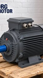
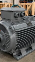
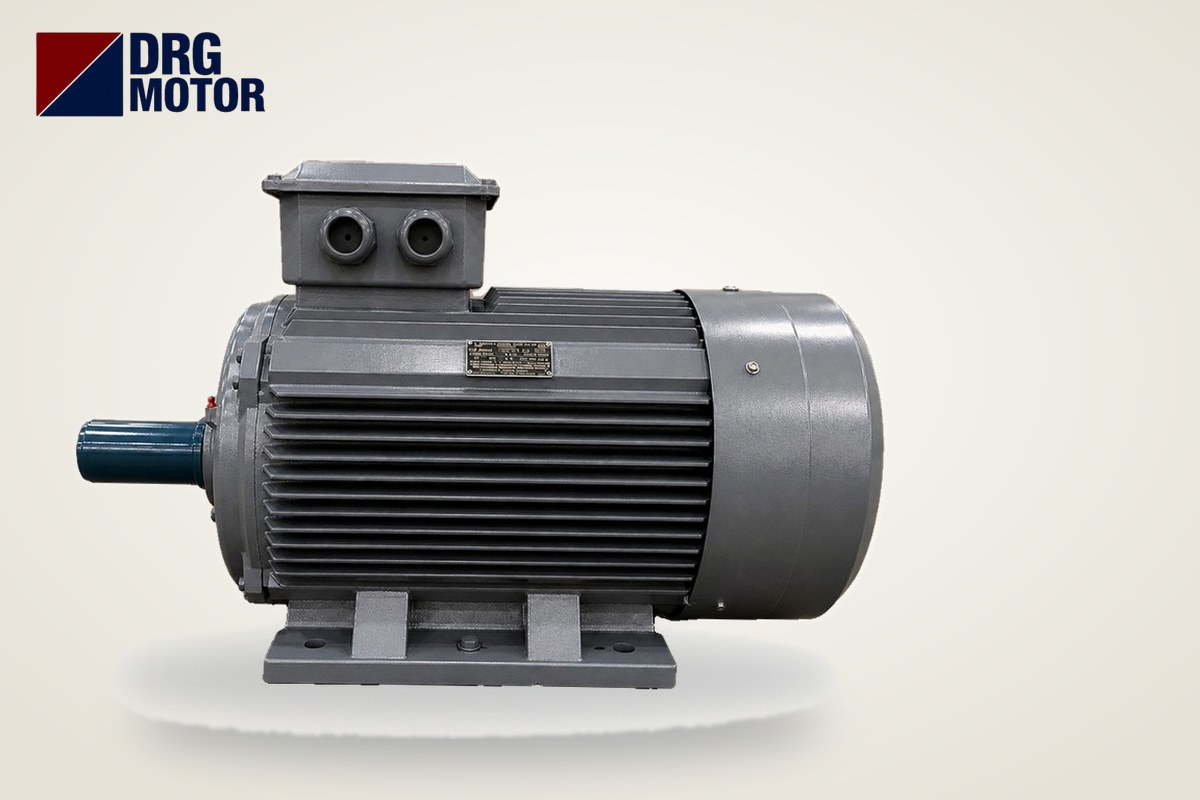

On a 380 V supply at full load, a 4-pole (1500 rpm) 55 kW motor draws about 103 A, a 75 kW motor 136 A and a 90 kW motor 163 A. At 400 V the same motors draw 97.6 A, 129 A and 155 A respectively. Current is slightly lower on 2-pole motors and slightly higher on 6-pole motors; all nine models are in the table below.
In this power class, knowing the current alone is not enough: with a load above 100 amps, reactive current, power factor correction and the kVA capacity of the supply (transformer or generator) become part of the same discussion. Below we illustrate all three with motor data. For the full technical pages of the models, see the Buy Electric Motors Online section.
55, 75 and 90 kW Motor Current Table (2, 4, 6 Poles)
All of these ratings in our store have cast iron frames and 400/690 V (Δ/Y) windings; on a 380–400 V supply they are connected in delta. The values are catalogue data:
| Model | kW | Speed (synchronous / rated) | cos φ | 380 V | 400 V | 415 V | Is/In |
|---|---|---|---|---|---|---|---|
| DRG-250M-2 | 55 | 3000 / 2970 rpm | 0.90 | 98.5 A | 93.5 A | 90.2 A | 7.7 |
| DRG-250M-4 | 55 | 1500 / 1485 rpm | 0.86 | 103 A | 97.6 A | 94.1 A | 7.4 |
| DRG-280M-6 | 55 | 1000 / 985 rpm | 0.86 | 103 A | 98.1 A | 94.6 A | 7.3 |
| DRG-280S-2 | 75 | 3000 / 2975 rpm | 0.90 | 134 A | 127 A | 122 A | 7.1 |
| DRG-280S-4 | 75 | 1500 / 1486 rpm | 0.88 | 136 A | 129 A | 125 A | 6.9 |
| DRG-315S-6 | 75 | 1000 / 985 rpm | 0.84 | 143 A | 136 A | 131 A | 6.6 |
| DRG-280M-2 | 90 | 3000 / 2975 rpm | 0.90 | 160 A | 152 A | 146 A | 7.1 |
| DRG-280M-4 | 90 | 1500 / 1486 rpm | 0.88 | 163 A | 155 A | 149 A | 6.9 |
| DRG-315M-6 | 90 | 1000 / 988 rpm | 0.85 | 170 A | 161 A | 155 A | 6.7 |
Two points stand out. First, at the same power the 6-pole motor always draws the highest current because its cos φ is lower (e.g. 0.84 at 75 kW). Second, at 55 kW the 4-pole and 6-pole models draw the same current at 380 V (103 A); both have a cos φ of 0.86. Current is determined not by kW alone but by power factor. Values for smaller ratings are in the motor current chart, and a detailed explanation for 37 and 45 kW is in the article on 37 and 45 kW motor current.
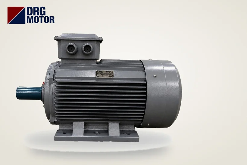
Reactive Current and cos φ in Large Motors
The current a motor draws has two components: active current that turns into work (I × cos φ) and reactive current that builds the magnetic field (I × sin φ). Reactive current transfers no power to the shaft, but it flows through the cable, the breaker and the transformer; it heats the cable and uses up transformer capacity. Calculation at 380 V, full load:
| Model | Current (380 V) | cos φ | sin φ | Active current (I·cos φ) | Reactive current (I·sin φ) |
|---|---|---|---|---|---|
| DRG-250M-2 | 98.5 A | 0.90 | 0.44 | ≈ 88.7 A | ≈ 42.9 A |
| DRG-250M-4 | 103 A | 0.86 | 0.51 | ≈ 88.6 A | ≈ 52.6 A |
| DRG-280M-6 | 103 A | 0.86 | 0.51 | ≈ 88.6 A | ≈ 52.6 A |
| DRG-280S-2 | 134 A | 0.90 | 0.44 | ≈ 120.6 A | ≈ 58.4 A |
| DRG-280S-4 | 136 A | 0.88 | 0.47 | ≈ 119.7 A | ≈ 64.6 A |
| DRG-315S-6 | 143 A | 0.84 | 0.54 | ≈ 120.1 A | ≈ 77.6 A |
| DRG-280M-2 | 160 A | 0.90 | 0.44 | ≈ 144.0 A | ≈ 69.7 A |
| DRG-280M-4 | 163 A | 0.88 | 0.47 | ≈ 143.4 A | ≈ 77.4 A |
| DRG-315M-6 | 170 A | 0.85 | 0.53 | ≈ 144.5 A | ≈ 89.6 A |
Example: the DRG-315S-6 draws 143 A at 380 V, of which ≈ 77.6 A is the reactive component. For the DRG-280S-2 of the same power the reactive component is ≈ 58.4 A. This difference does not mean the motor is poor; it comes from the design of low-speed motors. In addition, when a motor runs at part load its cos φ falls below the nameplate value and the reactive share grows further. That is why oversizing a large motor puts an unnecessary load on the supply.
Why Power Factor Correction Comes Up
Reactive current does not have to come from the grid; capacitors connected in the panel can supply it locally. This is called power factor correction. Once the capacitor is in circuit, the motor's reactive demand is met by the capacitor and the current flowing through the supply and feeder cable approaches the active current. Because grid rules limit the ratio of reactive to active consumption in industrial plants, the adequacy of the existing correction panel is always checked when a 55–90 kW motor is added.
The capacitor rating (kVAr) is calculated from the total plant load and the target power factor; no rule-of-thumb value is given for a single motor. In practice two things should be known: correction does not change the nameplate current of the motor (the overload relay is still set to nameplate current), and capacitors are not connected directly in front of a motor run by a frequency drive. For a detailed calculation, work with the electrical engineer who builds the correction panel.
kVA Calculation for Generators and Transformers: S = √3 × U × I
To see whether the supply can carry the motor, convert current into apparent power. For the DRG-280S-4 (75 kW, 4-pole) at 400 V:
- Rated operation: S = √3 × 400 V × 129 A ≈ 89.4 kVA
- Direct-on-line start (Is/In = 6.9): ≈ 617 kVA
- Star-delta start (≈ 1/3): ≈ 206 kVA
The motor delivers 75 kW of mechanical power but asks about 89 kVA of apparent power from the supply; the difference comes from cos φ and motor losses. An example with two motors running together: if 4-pole 55 kW (67.6 kVA) and 90 kW (107.4 kVA) motors are fed from the same transformer, the continuous load is ≈ 175.0 kVA; starts should not be simultaneous, and the larger motor should be started first.
| Model | Rated (400 V) | Direct-on-line start | Star-delta start |
|---|---|---|---|
| DRG-250M-2 | ≈ 64.8 kVA | ≈ 499 kVA | ≈ 166 kVA |
| DRG-250M-4 | ≈ 67.6 kVA | ≈ 500 kVA | ≈ 167 kVA |
| DRG-280M-6 | ≈ 68.0 kVA | ≈ 496 kVA | ≈ 165 kVA |
| DRG-280S-2 | ≈ 88.0 kVA | ≈ 625 kVA | ≈ 208 kVA |
| DRG-280S-4 | ≈ 89.4 kVA | ≈ 617 kVA | ≈ 206 kVA |
| DRG-315S-6 | ≈ 94.2 kVA | ≈ 622 kVA | ≈ 207 kVA |
| DRG-280M-2 | ≈ 105.3 kVA | ≈ 748 kVA | ≈ 249 kVA |
| DRG-280M-4 | ≈ 107.4 kVA | ≈ 741 kVA | ≈ 247 kVA |
| DRG-315M-6 | ≈ 111.5 kVA | ≈ 747 kVA | ≈ 249 kVA |
In generator-fed systems the starting column is decisive: how much short-term load a generator tolerates depends on its manufacturer's data, so this table should be used as starting data when talking to the generator supplier. At this rating direct-on-line starting is rarely chosen; star-delta, a soft starter or a frequency drive significantly reduces the starting kVA.
Starting Current and Overload Setting
At 380 V, direct-on-line starting current is In × Is/In: 55 kW 4-pole ≈ 762 A, 75 kW 4-pole ≈ 938 A, 90 kW 4-pole ≈ 1125 A. With star-delta these values drop to about one third (≈ 254 / 313 / 375 A). In a star-delta panel, if the overload relay is in the phase line it is set to In/√3: ≈ 59.5 A for 55 kW 4-pole, ≈ 78.5 A for 75 kW, ≈ 94.1 A for 90 kW. For contactor, fuse and overload sizes use the overload, fuse and contactor selection tool, and for the feeder cable the motor cable size calculator.
Cable Entry, Bearing and Shaft Data
The mechanical data site teams ask about most before replacing or installing a motor of this size are as follows, from the catalogue:
| Model | IEC frame | Shaft height H | Shaft diameter × length | Cable entry | Bearing |
|---|---|---|---|---|---|
| DRG-250M-2 | 250M | 250 mm | 60 × 140 mm | 2 × M63×1.5 | 6314-C3 |
| DRG-250M-4 | 250M | 250 mm | 65 × 140 mm | 2 × M63×1.5 | 6314-C3 |
| DRG-280M-6 | 280M | 280 mm | 75 × 140 mm | 2 × M63×1.5 | 6317-C3 |
| DRG-280S-2 | 280S | 280 mm | 65 × 140 mm | 2 × M63×1.5 | 6314-C3 |
| DRG-280S-4 | 280S | 280 mm | 75 × 140 mm | 2 × M63×1.5 | 6317-C3 |
| DRG-315S-6 | 315S | 315 mm | 85 × 170 mm | 2 × M63×1.5 | 6319-C3 |
| DRG-280M-2 | 280M | 280 mm | 65 × 140 mm | 2 × M63×1.5 | 6314-C3 |
| DRG-280M-4 | 280M | 280 mm | 75 × 140 mm | 2 × M63×1.5 | 6317-C3 |
| DRG-315M-6 | 315M | 315 mm | 85 × 170 mm | 2 × M63×1.5 | 6319-C3 |
All nine models have two M63×1.5 entries on the terminal box; because cable cross-sections are large at currents above 100 A, choose glands in advance according to the cable outer diameter. Note that the shaft of 2-pole models is thinner than that of 4- and 6-pole models in the same frame (e.g. on frame 280S, 65 mm for 2-pole, 75 mm for 4-pole); order couplings and pulleys by model code. If ambient temperature or altitude is high, see our derating article for current and power assessment.
Commissioning Checklist
- Nameplate voltage 400/690 V; on a 380–400 V supply the running connection is delta.
- Transformer or generator kVA capacity checked against rated and starting values.
- Adequacy of the correction panel for the new load assessed with the site electrical engineer; no capacitor connected in front of a drive-fed motor.
- Overload relay set to In or In/√3 according to where it is connected.
- Suitable glands ready for the cable entries (2 × M63); terminal connections tightened to torque.
- At first start, all three phase currents measured with a clamp meter and compared with nameplate current.
- Coupling alignment and bearing noise checked in the first hours.
Motors in These Ratings
55, 75 and 90 kW three-phase motors in our online store:
- DRG-250M-2 – 55 kW – 3000 rpm – cast iron, IEC 250M
- DRG-250M-4 – 55 kW – 1500 rpm – cast iron, IEC 250M
- DRG-280M-6 – 55 kW – 1000 rpm – cast iron, IEC 280M
- DRG-280S-2 – 75 kW – 3000 rpm – cast iron, IEC 280S
- DRG-280S-4 – 75 kW – 1500 rpm – cast iron, IEC 280S
- DRG-315S-6 – 75 kW – 1000 rpm – cast iron, IEC 315S
- DRG-280M-2 – 90 kW – 3000 rpm – cast iron, IEC 280M
- DRG-280M-4 – 90 kW – 1500 rpm – cast iron, IEC 280M
- DRG-315M-6 – 90 kW – 1000 rpm – cast iron, IEC 315M
Click to see current prices and order these motors nowSEE PRICES →
Frequently Asked Questions
How many amps does a 75 kW motor draw?
At 380 V full load, the 2-pole model draws 134 A, the 4-pole model 136 A and the 6-pole model 143 A. At 400 V the values are 127, 129 and 136 A respectively.
What size generator (kVA) does a 90 kW motor need?
A 4-pole 90 kW motor takes ≈ 107.4 kVA of apparent power at 400 V in rated operation; this rises to ≈ 741 kVA at direct-on-line start and ≈ 247 kVA at star-delta start. Generator capacity is chosen from these values and the generator manufacturer's starting data.
How many amps does a 55 kW motor draw?
At 380 V the 2-pole model draws 98.5 A and the 4- and 6-pole models 103 A. At 400 V the 4-pole model draws 97.6 A.
Does power factor correction reduce motor current?
The current through the motor's own winding does not change; what falls is the current flowing from the capacitor connection point towards the grid. The overload relay is therefore still set to the nameplate current.
For model, supply or starting method selection at high power, send us your application: +90 (542) 666 11 11, [email protected] or the contact page. You can browse all ratings among the 120 models in our online store.