English
 Le français
 Türkçe




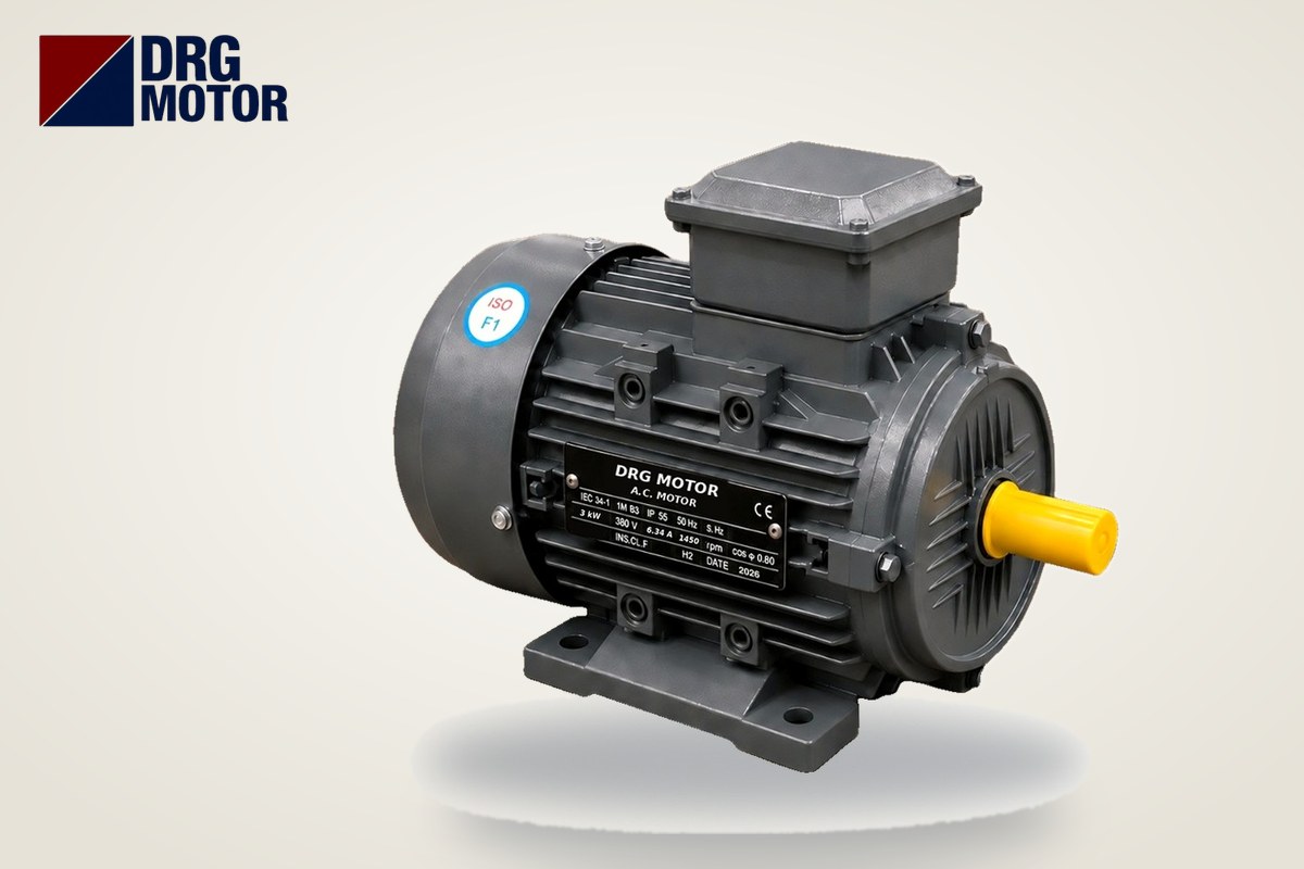

When an electric motor will not run, the fastest way to find the fault is to first identify how it fails: if there is no sound at all, the problem is most likely in the supply or control circuit (fuse, breaker, contactor coil, emergency stop, overload contact); if the motor hums but does not turn, look for a missing phase, a seized shaft or a wrong terminal connection; if it starts and trips immediately, check the protection setting, overload, or a winding/insulation fault. The measuring order is always the same: phase-to-phase voltage in the panel, voltage at the motor terminals, winding resistance balance with the power off, and finally the insulation test.
This work must be done by a qualified electrician. Before the terminal box is opened, the motor isolator is switched off, locked and tagged (lockout-tagout), and absence of voltage is confirmed with a tester. On drive-fed (inverter) systems, wait the time stated by the drive for the DC bus capacitors to discharge. If the diagnosis shows the motor must be replaced, you can choose the matching power, speed and frame among the 120 models on our Buy Electric Motors Online page by comparing nameplate values.
The method below splits the three most common field symptoms into separate branches. This avoids wasted work and downtime from wrong decisions such as removing a healthy motor and sending it to the workshop, or buying a new motor when the real culprit is a faulty contactor.
Why Is the Motor Not Running? Three Cases by Symptom
Press the start button, listen to the motor and watch the panel. Whether the contactor pulls in (a firm “clack”), whether the motor hums, and how quickly the protection trips largely tell you where the fault is.
| Symptom | Possible cause | First check |
|---|---|---|
| No sound, contactor does not pull in | Control fuse, emergency stop, overload contact (95-96), contactor coil, control wiring | Control voltage and continuity of the stop chain |
| No sound, contactor pulls in | Power fuse/breaker, contactor main contacts, broken motor cable | Phase-to-phase voltage at the contactor output and motor terminals |
| Hums, does not turn | Missing phase, mechanical seizure, 400/690 V motor connected in star, heavy load | All three phases present, does the shaft turn by hand, terminal links |
| Runs, trips within seconds | Wrong overload setting, overload, 230/400 V motor connected in delta, low voltage | Three phase currents (clamp meter) compared with the nameplate current |
| Breaker trips instantly | Short circuit, winding-to-frame fault, earth leakage | Winding resistance and insulation test with the power off |
No Sound at All: Check the Supply and Control Circuit in Order
If the motor makes no sound, the motor itself is usually innocent; power simply never reaches it. Work from the panel towards the motor, following the path of the energy:
- Main supply: Measure L1-L2, L2-L3 and L3-L1 at the panel incomer. On a 380 V network the three values should be close to each other.
- Power fuses or motor protection circuit breaker: Check for voltage at the input and output of each fuse; a single blown fuse leaves the motor on two phases and the symptom moves to the “humming” branch.
- Control circuit: The control fuse, the emergency stop (a mushroom button may be latched), the normally closed stop contact and the overload relay contact 95-96 form a series chain. One open point in the chain prevents the contactor coil from being energised.
- Contactor coil: If control voltage is present at the coil terminals (A1-A2) but the contactor does not pull in, the coil is faulty or its voltage does not match the circuit (for example a 24 V coil connected to a 230 V control circuit and burnt).
- Contactor output and motor cable: If the contactor pulls in, measure the voltage at its outputs (T1-T2-T3) and then at the motor terminals. Voltage in the panel but not at the terminals indicates a broken cable or a loose lug.
If the overload relay is set to manual reset after tripping, the motor will not run at all until it is reset. For the setting and operating principle, see our article What Does a Thermal Overload Relay Do?
Motor Hums but Does Not Turn: Missing Phase, Seized Shaft, Wrong Connection
Humming means the windings are energised but either no rotating field is formed or the torque is not enough to move the load. Do not leave the motor energised for long: with a locked rotor the motor draws several times its rated current and the winding heats up quickly.
Missing phase
If one of the three phases is missing, a three-phase motor cannot start from standstill; it only hums. Measure the three phase-to-phase voltages at the terminals separately; if two readings are low or zero, you have found the missing phase. The usual source is a single blown fuse, a burnt contactor contact or a loose terminal screw.
Mechanical seizure
After isolating and locking off, disconnect the coupling or pulley and turn the motor shaft by hand. If the shaft turns freely, the problem is in the driven machine (jammed pump impeller, locked gearbox, over-tensioned belt). If the shaft does not turn or feels rough, suspect the bearing or rotor-stator rubbing; details in our article How to Tell Motor Bearing Failure.
Wrong terminal connection
A motor whose nameplate reads 400/690 V (Δ/Y) must be connected in delta on a 380 V network. If it is connected in star by mistake, each winding sees about 380/√3 ≈ 219 V, and because torque falls with the square of the voltage, starting torque drops to one third. For example, the catalogue gives Ts/Tn = 2.2 and a rated torque of 26.3 Nm for the DRG-112M-4 (4 kW, 1450 rpm); with the correct connection the starting torque is about 2.2 × 26.3 ≈ 57.9 Nm, while with the wrong star connection it falls to about 19.3 Nm. A motor that can spin unloaded cannot start under load and just hums. For the link arrangement, see our article Motor Terminal Connection: Star and Delta.
Motor Runs but Trips Immediately: Overload, Fuse or Earth Leakage?
Which protective device trips tells you the type of fault, so note the tripped device before resetting.
- Overload relay trips after a few seconds or minutes: The setting may be below the nameplate current, the motor may really be overloaded, or a phase is missing. Measure the three phase currents with a clamp meter and compare them with the nameplate In. If a motor marked 230/400 V (Δ/Y) is connected in delta on 380 V, the windings see excessive voltage, current rises and the overload trips.
- Fuse or breaker trips instantly at start: Starting current is normally several times the rated current (Is/In in the data sheet); the protection may be too small to carry it. Detailed causes are in our article Why Does an Electric Motor Trip the Fuse?; you can check suitable overload, fuse and contactor values with our Overload, Fuse and Contactor Selection tool.
- Earth leakage (RCD) trips: Look for leakage from winding to frame, a damp terminal box or damaged cable insulation. The insulation test is decisive here.
Measuring Order: From Voltage to Winding Resistance and Insulation
Order the measurements from easy to difficult, and finish the live measurements before moving on to the de-energised ones. Write every value down; the decision to repair or replace the faulty motor is made from these records.
1. Phase-to-phase voltage and unbalance calculation
Suppose you measure L1-L2 = 392 V, L2-L3 = 381 V and L3-L1 = 374 V at the motor terminals. The average is (392 + 381 + 374) / 3 ≈ 382.3 V; the largest deviation from the average is 392 − 382.3 ≈ 9.7 V. Voltage unbalance ≈ 9.7 / 382.3 × 100 ≈ 2.5%. Because a small voltage unbalance causes a much larger current unbalance, the source of a difference at this level (load distribution, loose connection, supply line) should be investigated. Phase-to-neutral voltage on a 380 V system is about 219 V; measuring only phase-to-neutral instead of phase-to-phase can hide a missing phase.
2. Winding resistance (balance) with the power off
Remove the cable connection and the links, and measure the U1-U2, V1-V2 and W1-W2 windings separately with an instrument that can read low ohms. The absolute value depends on motor power; what matters is that the three windings are close to each other. For example, readings of 3.10 Ω, 3.12 Ω and 3.41 Ω give an average of 3.21 Ω and a largest deviation of about 6.2%: the third winding is suspected of a turn-to-turn short or a loose internal connection. A winding that reads infinite (open circuit) is broken.
3. Insulation resistance (megger)
The insulation test is done with a megger (insulation tester), which applies a high DC test voltage between winding and frame and between windings; an ordinary multimeter is not sufficient for this measurement. The acceptance value depends on the rated voltage of the motor, temperature and humidity; refer to the instrument manual and the relevant standard for the test voltage and limits. Drives, capacitors and electronic protection devices must be disconnected during the test. Method details are in our article Insulation Resistance (Megger) Test on Electric Motors; if the readings show a burnt winding, move on to the decision steps in How to Tell if a Three-Phase Motor Is Burnt.
Comparing with Nameplate Values: Is Your Measured Current Normal?
Once the motor turns, compare the current read with the clamp meter with the nameplate value. The high current at start-up is also a criterion: the protective device must carry it for the duration of the start. The values below are taken from DRG catalogue data (380 V); starting current is calculated as Is = In × (Is/In).
| Model | Power | Nameplate voltage | Connection at 380 V | In (380 V) | Is/In | Approx. starting current |
|---|---|---|---|---|---|---|
| DRG-100L2-4 | 3 kW | 230/400 V | Star | 6.34 A | 7.6 | ≈ 48.2 A |
| DRG-112M-4 | 4 kW | 400/690 V | Delta | 8.37 A | 7.8 | ≈ 65.3 A |
| DRG-132M-4 | 7.5 kW | 400/690 V | Delta | 15.0 A | 7.5 | ≈ 112.5 A |
| DRG-160L-4 | 15 kW | 400/690 V | Delta | 28.8 A | 7.8 | ≈ 224.6 A |
| DRG-180L-4 | 22 kW | 400/690 V | Delta | 41.8 A | 7.8 | ≈ 326.0 A |
All models in the table are 1500 rpm (4-pole) with a cast iron frame. If the measured running current is close on all three phases and below the nameplate current, the motor is electrically healthy; the reason for tripping lies in the protection setting or on the load side. For the rated currents of other powers, use our Motor Current Chart tool.
Electric Motor Fault Finding Checklist
- Isolator switched off, locked and tagged; absence of voltage confirmed with a tester.
- Tripped protective device noted (overload, fuse, breaker, earth leakage).
- Three phase-to-phase voltages measured at the panel incomer and motor terminals, unbalance calculated.
- Control chain (control fuse, emergency stop, stop button, overload 95-96) checked for continuity.
- Contactor coil voltage and main contact outputs checked.
- Terminal links verified against the nameplate voltage (230/400 V → star on 380 V; 400/690 V → delta on 380 V).
- Coupling/belt disconnected and shaft turned by hand; machine side tried separately.
- Winding resistances U1-U2, V1-V2, W1-W2 measured and compared.
- Insulation test done with a megger, electronic devices disconnected.
- On restart, three phase currents measured and compared with the nameplate In.
If the Motor Must Be Replaced: Three-Phase Models with the Same Ratings
If the measurements confirm a winding or insulation fault, the new motor must have the same nameplate voltage, connection, speed and frame size as the old one; otherwise the panel and the mechanical connection change too. Commonly used 4-pole models:
- DRG-100L2-4 – 3 kW – 1500 rpm – 100L cast iron
- DRG-112M-4 – 4 kW – 1500 rpm – 112M cast iron
- DRG-132M-4 – 7.5 kW – 1500 rpm – 132M cast iron
- DRG-160L-4 – 15 kW – 1500 rpm – 160L cast iron
- DRG-180L-4 – 22 kW – 1500 rpm – 180L cast iron
Click to see current prices and order these motors nowSEE PRICES →
Frequently Asked Questions
Why does my electric motor hum but not turn?
The most common cause is a missing phase: when one of the three phases is absent, a three-phase motor cannot start from standstill. Next come mechanical seizure (bearing, jammed machine) and a 400/690 V motor connected in star on 380 V. Do not leave the motor humming; switch off and check the three phase-to-phase voltages at the terminals and whether the shaft turns by hand.
My three-phase motor makes no sound at all. Where should I start?
Check whether the contactor pulls in. If it does not, check the control chain (control fuse, emergency stop, stop button, overload contact, coil); if it does, measure the power fuses, the contactor output and the voltage at the motor terminals. In this case the motor winding is usually healthy.
Can a motor fault be found with a multimeter?
Partly. A multimeter can measure voltage, continuity and winding resistance balance; a broken winding or a clear resistance difference can be found this way. Weak insulation between winding and frame, however, needs a high test voltage and is measured with a megger.
The motor runs but the overload trips. Is the motor burnt?
Not always. First check that the overload setting matches the nameplate current, that the three phases arrive balanced and that the motor is not overloaded. If the measured current is below the nameplate value and the phases are balanced, the problem is most likely the setting or the relay; unbalanced winding resistances or weak insulation point more strongly to a motor fault.
After the diagnosis, you can send us a photo of the nameplate to select a suitable replacement motor: +90 (542) 666 11 11 · [email protected] · Contact. All power and speed options are on our Buy Electric Motors Online page; for other calculations, see Electric Motor Calculators.