English
 Le français
 Türkçe




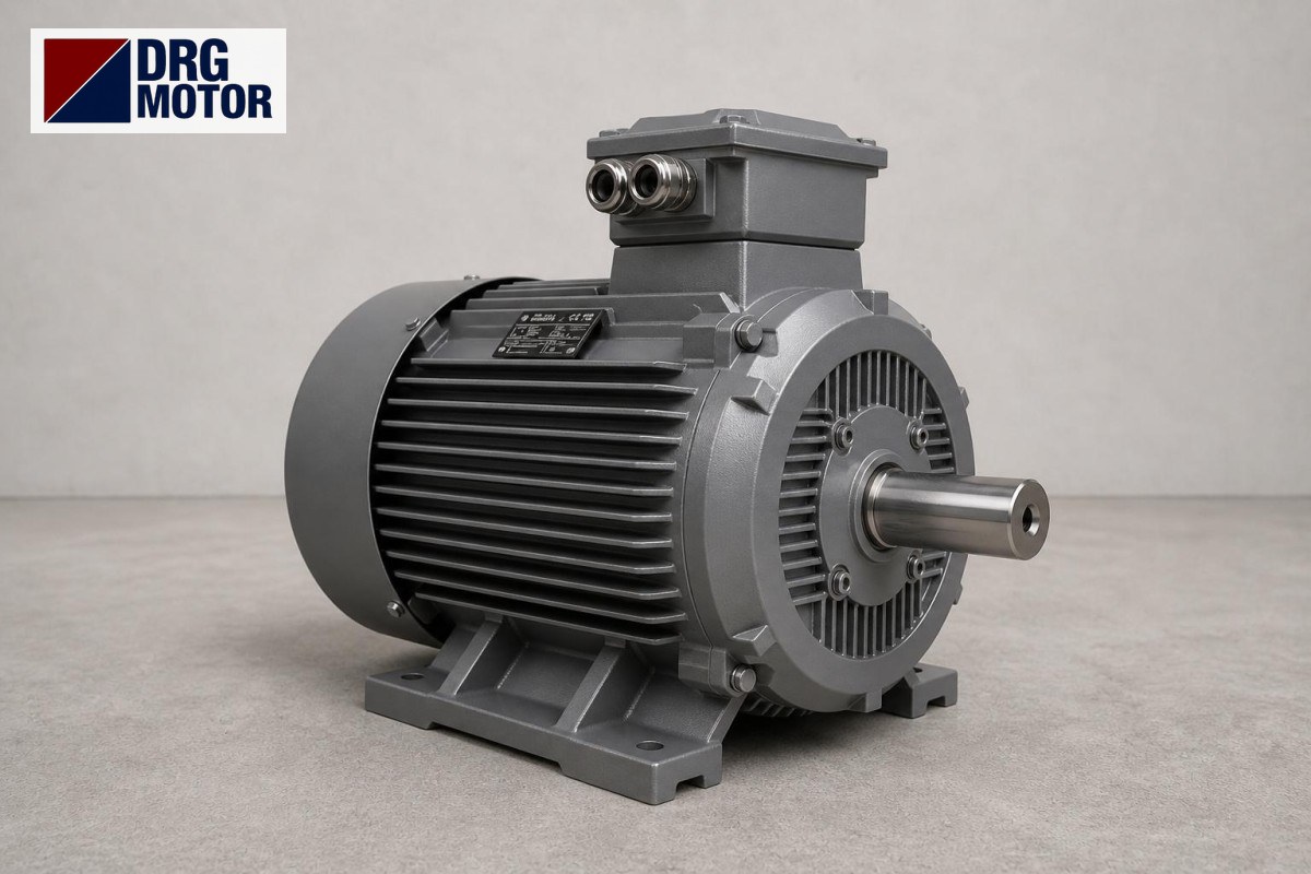

When looking for an 18.5 kW flanged motor, the decision is usually between B5 and B35, and at this power the balance tips towards B35. The reason is that 18.5 kW frames are large: the 3000 rpm DRG-160L-2 is 652 mm long in a 160L frame, the 1500 rpm DRG-180M-4 688 mm in a 180M frame and the 1000 rpm DRG-200L1-6 779 mm in a 200L frame, and all three are cast iron. Hung on the flange alone, this whole mass rests on the flange bolts as a cantilever load; in B35 the feet carry the weight and the flange only sets the axis.
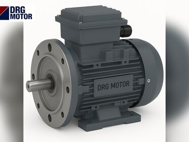
B35 combines B3 feet and a B5 flange on the same motor. A B35 order therefore needs two separate groups of dimensions to be right: on the foot side H, A, B, C and K; on the flange side P, M, N, S and the shaft. Below we give the two groups in separate tables.
The codes link to the three product pages; all powers and speeds are on the Buy Electric Motors Online page.
Foot side: B3 dimensions
| Model | Shaft height H | Foot hole spacing A × B | C (shaft shoulder–foot hole) | Foot holes K | Overall length L |
|---|---|---|---|---|---|
| DRG-160L-2 | 160 | 254 × 254 | 108 | 4–Φ14.5 | 652 |
| DRG-180M-4 | 180 | 279 × 241 | 121 | 4–Φ14.5 | 688 |
| DRG-200L1-6 | 200 | 318 × 305 | 133 | 4–Φ18.5 | 779 |
H is the height from the foot base to the shaft axis and equals the frame number. A is the transverse and B the longitudinal hole spacing between the feet; C is the distance from the shaft shoulder to the first foot hole. B is 241 mm on 180M but 254 mm on 160L; although the 4-pole model sits in a taller frame, its longitudinal foot spacing is shorter. If the base holes were drilled for the old motor, this small difference calls for new holes.
Change the speed and the axis height changes too
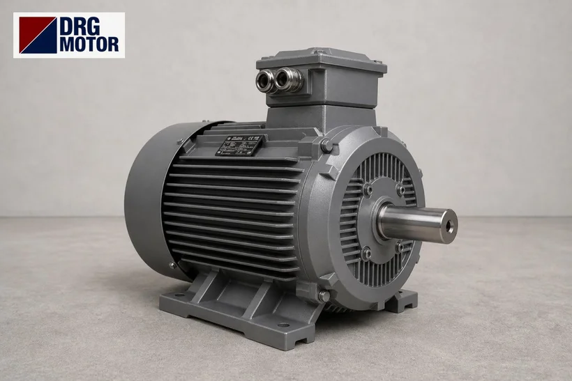
At 18.5 kW the three models have different shaft heights: 160, 180 and 200 mm. When a machine moves to a model of another speed, for example from the 3000 rpm 160L to the 1500 rpm 180M, the shaft axis rises 20 mm relative to the foot base; moving to the 200L the difference is 40 mm. In B35 mounting this difference causes trouble in two places: since the flange spigot is located on the machine axis, the feet do not touch the base, or if the feet are seated the flange cannot enter its recess.
The other way round, going from a taller to a lower frame, a raising plate is needed under the feet; from 180M to 160L a 20 mm plate machined parallel on both faces closes the gap. Making up this much height with a thin shim pack is not right; shims settle under load and spoil the alignment over time. If the frame changes, the base and the flange recess must be reconsidered together.
Flange and shaft side: B5 dimensions
| Model | Speed | B5 flange P / M / N | S / LA | Shaft D × E | Key F / DH | Order |
|---|---|---|---|---|---|---|
| DRG-160L-2 (160L) | 2940 rpm | 350 / 300 / 250 | 18.5 / 15 | 42 × 110 | 12 / M16X36 | See Prices |
| DRG-180M-4 (180M) | 1470 rpm | 350 / 300 / 250 | 18.5 / 15 | 48 × 110 | 14 / M16X36 | See Prices |
| DRG-200L1-6 (200L) | 980 rpm | 400 / 350 / 300 | 18.5 / 17 | 55 × 110 | 16 / M20X42 | See Prices |
The 160L and 180M frames share the same flange (P 350 / M 300 / N 250 mm). On the 200L the flange goes up a class: P 400, M 350, N 300 mm, LA 17 mm. The shaft also grows from 42 to 48 and, on the 6-pole, to 55 mm. For all available dimensions see our B5 flange dimensions table, and for the general B3 versus B35 decision our article B3 or B35.
Why foot support on a heavy motor?
Think of a motor carried by the flange alone as a beam projecting from the flange face. As a rough lever arm we can take half of the body length from flange to rear cover (LB): 542 / 2 ≈ 271 mm on 160L, 578 / 2 = 289 mm on 180M, 669 / 2 ≈ 335 mm on 200L. Multiplied by the motor weight, this arm produces a moment that tries to bend the flange bolts; the heavier and longer the body, the larger that moment.
Vibration and starting add to it. On the 18.5 kW models starting torque is 2.0 times rated; at start about 120.2 × 2.0 ≈ 240 Nm on the 180M and 180.3 × 2.0 ≈ 361 Nm on the 200L try to turn the housing the other way. With flange-only mounting this reaction also goes into the bolts. In B35 the foot bolts share both the weight and this reaction, leaving the flange free to do the centring.
When is B5 still suitable?
- When the part the motor bolts to (pump casing, lantern bracket, gearbox input) is designed rigid enough to carry the motor.
- When the motor will run vertically and its weight acts along the axis onto the flange (V1 position).
- When there is simply no surface for feet to rest on in the layout.
Even then, the machine builder should confirm that the mating part can carry an 18.5 kW frame. In geared applications, check the "largest permissible motor" in the gearbox catalogue; this is covered separately in our article on choosing a flanged motor for a gearbox.
B35 mounting sequence: avoiding strain in a double connection
In B35 the motor is fixed in two planes, and if these two planes are not exactly in position relative to each other, the housing is strained. In practice the safe sequence is:
- First seat the flange spigot in its recess and tighten the flange bolts by hand.
- Measure the gap under each foot separately; close it with shims rather than pulling the feet down to the base.
- Fully tighten the flange bolts in a cross pattern.
- Then tighten the foot bolts while checking with a dial gauge that the shaft end does not move.
- If the shaft does not turn freely by hand, loosen the foot bolts and re-shim.
Even a few tenths of a millimetre between the foot-to-axis height (H) and the real height on the machine is loaded into the housing and bearings when the foot bolt is tightened. The bearings are 6309-C3 on 160L, 6311-C3 on 180M and 6312-C3 on 200L.
What to know on the electrical side
All 18.5 kW models are wound for 400/690 V (Δ/Y) and run in delta at 380 V. Rated current at 400 V is 32.5 A (2-pole), 33.5 A (4-pole), 35.9 A (6-pole); cos φ is 0.89, 0.86, 0.81. Starting current ratios are 8.2, 7.8, 7.3. For overload setting and contactor choice, use the overload and contactor selection tool; the connection must be made by a qualified electrician.
Technical differences reflected in the price
At 18.5 kW all three models are cast iron. What separates them is the number of poles and the frame (160L, 180M, 200L), plus the mounting: B5 is flange only, while B35 carries feet and flange together. The 200L frame and larger flange of the 6-pole model mean more material. Open these codes among the 120 models in our shop to see their current status.
B35 order checklist
- Which model matches the foot hole spacing A × B on the base: 254 × 254, 279 × 241 or 318 × 305?
- Do the foot bolts suit 14.5 mm holes (160, 180) or 18.5 mm holes (200)?
- Is the flange recess 250 mm or 300 mm?
- Is the coupling hub for a 42, 48 or 55 mm shaft?
- Does the axis height on the machine match the motor's H (160, 180, 200 mm), with room for shims?
- Will the motor run horizontally or vertically?
- Is "B35" clearly written in the order?
18.5 kW models
- DRG-160L-2 | 18.5 kW | 2940 rpm | 160L cast iron
- DRG-180M-4 | 18.5 kW | 1470 rpm | 180M cast iron
- DRG-200L1-6 | 18.5 kW | 980 rpm | 200L cast iron
Click to see current prices and order these motors nowSEE PRICES →
Frequently Asked Questions
What frame size is an 18.5 kW motor?
The DRG 18.5 kW models are 160L at 3000 rpm, 180M at 1500 rpm and 200L at 1000 rpm; all three are cast iron.
What is the shaft diameter of a 25 HP motor?
On the 18.5 kW (25 HP) models the shaft is 42 × 110 mm on 160L, 48 × 110 mm on 180M and 55 × 110 mm on 200L.
What is a B35 motor?
B35 combines foot mounting (B3) and flange mounting (B5) on the same motor. The feet carry the weight and reaction torque, while the flange centres the motor on the machine axis.
Can I use a B5 motor as B35?
No; a B5 housing has no feet. If B35 is required, the order must be placed as B35. A separate support bracket can be designed to carry an existing B5 motor, but it is not part of the motor housing.
Send us the hole dimensions of your base and your flange recess and we will choose the right 18.5 kW B35 model together. Contact: +90 (542) 666 11 11, [email protected], drgmotor.com/en/contact. Other powers are available in the Buy Electric Motors Online section.