English
 Le français
 Türkçe




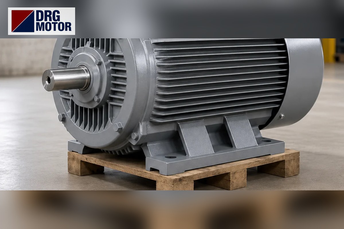

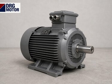
If you are preparing a base frame, start with these dimensions: the DRG-200L-4, the 40 HP 1500 rpm motor, has foot holes spaced 318 mm across and 305 mm lengthwise, a hole diameter of 18.5 mm, and its shaft centre is 200 mm above the mounting surface. The shaft is 55 × 110 mm with a 16 mm key; overall length is 779 mm and height including the terminal box (HD) is 499 mm.
The motor is 30 kW, 4-pole, in a cast-iron 200L frame; at full load it turns at 1475 rpm, delivers 194.2 Nm and draws 56.6 A at 380 V. Its bearing is a 6312-C3. At this power, mechanical installation errors (soft foot, misaligned coupling, loose foundation bolts) shorten bearing life more often than electrical problems do; that is why this page focuses mainly on dimensions, base frame and bearings.
The current price and ordering details of the DRG-200L-4, manufactured and supplied by DRG Motor, are on its product page in the Buy Electric Motors Online category.
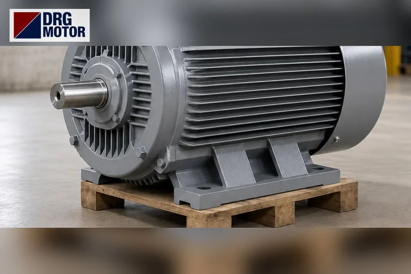
B3 mounting dimensions and what they determine
| Dimension | mm | Meaning for base frame/installation |
|---|---|---|
| A | 318 | Foot hole spacing across – centre distance of base rails |
| B | 305 | Foot hole spacing lengthwise |
| C | 133 | Shaft shoulder to front foot hole – coupling gap |
| H | 200 | Shaft centre height – matching the driven machine |
| K | 4–Φ18.5 | Foundation bolt hole |
| D × E | 55 × 110 | Coupling/pulley hub bore and length |
| F | 16 | Key width |
| AC | 397 | Frame diameter – side clearance |
| AD | 299 | Shaft centre to top of terminal box |
| L | 779 | Overall length – leave air space behind the fan cover |
The centre hole thread at the shaft end is M20X42 (B5 catalogue table, DH). If the coupling or pulley is fitted with a puller screwed into this thread, the bearing is not hammered; the same thread is used for removal.
Base frame design: the effect of 194 Nm on the feet
The torque produced by the motor tries to turn the frame in the opposite direction; this reaction passes into the base as a force couple between the two rows of feet. An approximate value is F ≈ T / A (A = 0.318 m):
| Condition | Torque | Reaction force between foot rows |
|---|---|---|
| Rated operation | 194.2 Nm | ≈ 611 N |
| Direct start (Ts/Tn 2.0) | ≈ 388 Nm | ≈ 1221 N |
| Breakdown torque (Tmax/Tn 2.3) | ≈ 447 Nm | ≈ 1405 N |
These forces are not large, but they repeat as a reversing impact at every start. With a belt drive, the horizontal pull of belt tension is added. Practical consequences:
- Make the base profile continuous under the feet; do not bolt the motor to thin sheet, which flexes at start.
- For a Φ18.5 mm hole, an M16 foundation bolt with a hardened washer is a common choice; bolt grade and tightening torque should be set by the base designer.
- For belt drives, seat the motor on slide rails; tension should be adjusted with the rail screw, not by shifting the motor feet on the base.
- On bases set on concrete plinths, tighten anchor bolts after grouting; bolts tightened too early loosen as the grout shrinks.
Soft foot and alignment
If one of the four feet does not sit fully on the base ("soft foot"), tightening the bolt slightly distorts the frame and ovalises the bearing housing. To check: tighten all bolts, then loosen them one by one while measuring foot lift with a dial gauge. Put stainless shims under any foot that moves more than 0.05 mm. A shim pack should have no more than 3–4 pieces; a pack of many thin shims settles over time.
In coupling alignment, if the 200 mm shaft height does not match the driven machine's shaft height, the difference is made up with a foot plate. Align with the motor cold; if a pump or fan casing running hot has thermal growth, apply the cold offset given by the machine builder.
Bearing 6312-C3: why C3 and what to watch
C3 indicates that the bearing is made with a larger internal clearance than standard. At operating temperature the shaft and inner ring expand; C3 clearance absorbs this expansion and prevents the bearing from binding. When replacing, use the same clearance class (6312-C3), not a normal-clearance 6312.
- Do not choose an unnecessarily small pulley: a small pulley transmits the same power with higher belt force, increasing the radial load on the front bearing.
- Fit the pulley close to the shaft shoulder; a pulley overhanging the shaft end lengthens the load arm.
- When fitting a coupling, heat the hub or push it on with a puller via the M20 thread; do not hammer it.
- If bearing noise and vibration are measured and recorded at commissioning, later changes are easy to spot.
Dimension comparison when replacing an old motor
When replacing a running 30 kW motor, you find out whether the new one will fit the same base not by looking at the rated power but by comparing four dimensions. If the IEC frame number is the same (200L), foot dimensions are the same too; but if the old motor was built to another standard or its nameplate is unreadable, measuring is essential.
- Shaft height (H): Measure from the mounting surface to the shaft centre. If it is not 200 mm, the axis no longer lines up with the driven machine; a few millimetres can be shimmed, more needs an adapter plate.
- Foot hole spacing (A × B): Measure between hole centres. Anything other than 318 × 305 mm means drilling new or slotted holes in the base.
- Shaft diameter and key (D, F): A coupling hub that does not fit a 55 mm shaft and 16 mm key must be re-machined or replaced. If you plan to bore out a hub made for a smaller shaft, ask the coupling supplier whether there is enough wall thickness.
- Dimension C: 133 mm from the shaft shoulder to the front foot hole. If this differs, the gap between coupling halves changes even when the motor bolts to the same holes.
If these four dimensions match, the motor will in most cases fit without drilling. Also check that the cable entry is 2 × M50×1.5, that the terminal box (AD 299 mm) does not hit surrounding guards, and that air can circulate freely behind the fan cover. Writing the dimensions down before removal reduces surprises on the base and shortens downtime once the old motor is out.
Electrical data (summary)
On this installation-focused page, the electrical values in brief: current 56.6 A at 380 V, 53.8 A at 400 V, 51.8 A at 415 V; cos φ 0.86; Is/In 7.3 (about 413 A at direct start on 380 V); Ts/Tn 2.0; Tmax/Tn 2.3; winding 400/690 V (Δ/Y), delta at 380 V; cable entry 2 × M50×1.5. Slip (1500 − 1475) / 1500 ≈ 1.7%, torque check 9550 × 30 / 1475 ≈ 194.2 Nm. To compare with other powers see the motor current chart, and for cable sizing one step up see 37 and 45 kW motor cable size selection. Electrical connection must be done by a qualified electrician.
Models sharing the same 200L frame
In the 200L frame the B3 dimensions (A 318, B 305, C 133, H 200, D 55, L 779) are identical on five models (2, 4 and 6 poles; 18.5–37 kW). This makes it easy to change speed or power on the same base:
- DRG-200L-4 – 30 kW – 1475 rpm – 200L cast iron
- DRG-200L1-2 – 30 kW – 2960 rpm – 200L cast iron
- DRG-200L2-2 – 37 kW – 2960 rpm – 200L cast iron
- DRG-225S-4 – 37 kW – 1485 rpm – 225S cast iron (base changes: A 356, H 225)
- DRG-180L-4 – 22 kW – 1470 rpm – 180L cast iron
The technical factors that set the price are power, number of poles, frame, mounting type (B3, B5 or B35) and protection rating. In the flanged (B5) version the 200L flange is P 400, M 350, N 300, S 18.5, T 5, LA 17 mm. For geared applications, output speed and torque can be found with the gearbox output speed calculator.
Click to see current prices and order these motors nowSEE PRICES →
Frequently Asked Questions
What are the foot hole dimensions of a 30 kW 4-pole motor?
On the DRG-200L-4 the foot hole spacing is 318 × 305 mm, hole diameter 18.5 mm and shaft height 200 mm.
Which bearing does a 40 HP motor have?
The DRG-200L-4 uses a 6312-C3 bearing. Keep the C3 clearance class when replacing it.
How many amps does a 40 HP 1500 rpm motor draw?
56.6 A at 380 V and 53.8 A at 400 V at full load. With direct-on-line starting, the starting current is about 413 A at 380 V.
What is the shaft size of a 30 kW motor?
The shaft is 55 × 110 mm, key width 16 mm, shaft end thread M20X42.
For dimension confirmation or technical questions on the DRG-200L-4, call +90 (542) 666 11 11 or write to [email protected]; all channels are on the contact page. Other powers and speeds are among the 120 models in our online store.