English
 Le français
 Türkçe




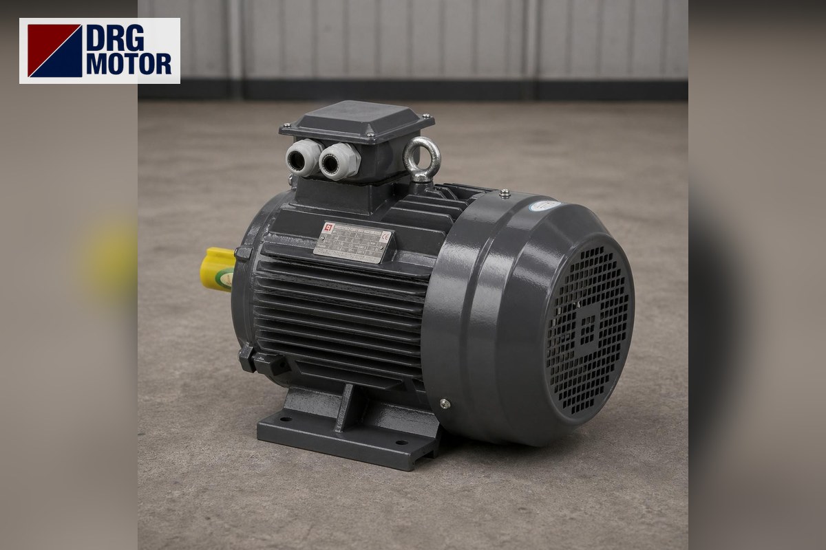

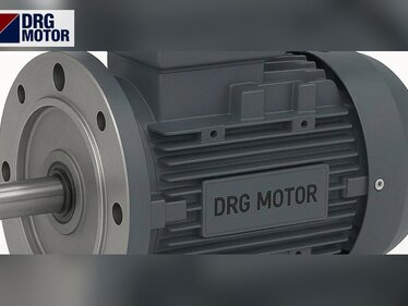
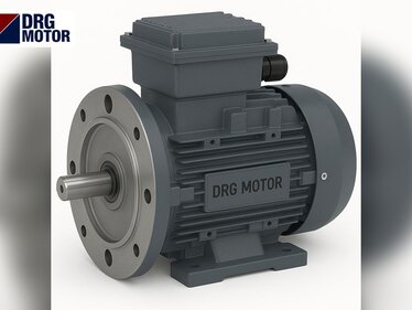
A 22 kW (30 HP) flanged motor comes in three frames, and the flange changes with the frame: the 3000 rpm DRG-180M-2 in 180M and the 1500 rpm DRG-180L-4 in 180L carry a P 350 / M 300 / N 250 mm B5 flange and a 48 × 110 mm shaft; the 1000 rpm DRG-200L2-6 in 200L moves to a P 400 / M 350 / N 300 mm flange and a 55 × 110 mm shaft. All three are cast iron.
This is the power at which the limits of flange-only mounting start to show. The catalogue gives B5 dimensions up to the 355 frame, so large flanged motors can be built; but at 22 kW, saying "make it B5" without considering together the torque carried by the flange, the body length behind the flange and the starting shock is risky. Below we work through these three points with the data.
Model details are on the product pages; other options are in the Buy Electric Motors Online category.
Flange data for the 180M, 180L and 200L frames
| Model | Frame | Speed | Flange P / M / N | LA | Shaft D × E | Body behind flange LB | Price |
|---|---|---|---|---|---|---|---|
| DRG-180M-2 | 180M | 2955 rpm | 350 / 300 / 250 | 15 | 48 × 110 | 578 | See Prices |
| DRG-180L-4 | 180L | 1470 rpm | 350 / 300 / 250 | 15 | 48 × 110 | 616 | See Prices |
| DRG-200L2-6 | 200L | 980 rpm | 400 / 350 / 300 | 17 | 55 × 110 | 669 | See Prices |
LB is the body length from the flange face to the rear end of the motor; it shows how much mass "hangs" relative to the flange. It is 578 mm on 180M, 616 mm on 180L and 669 mm on 200L. On the 200L the flange thickness LA rises to 17 mm and the bolt circle to 350 mm; the larger frame comes with a larger flange.
Three limits of flange-only mounting
1. How does torque pass through the flange?
In flange-only mounting, the reaction to the motor torque passes from the housing to the flange, then to the bolts and the mating part. To get a rough idea, divide the torque by the bolt circle radius to find the tangential force (F = T / r). This is the total force, shared according to the number of bolts and friction; it does not replace a design calculation, but it shows the order of magnitude:
| Model | Rated torque | Bolt circle radius | Tangential force (rated) | At start (Ts/Tn) | At breakdown torque (Tmax/Tn) |
|---|---|---|---|---|---|
| DRG-180M-2 | 71.1 Nm | 150 mm | ≈ 474 N | 2 → ≈ 948 N | 2.3 → ≈ 1,090 N |
| DRG-180L-4 | 142.9 Nm | 150 mm | ≈ 953 N | 2 → ≈ 1,905 N | 2.3 → ≈ 2,191 N |
| DRG-200L2-6 | 214.4 Nm | 175 mm | ≈ 1,225 N | 2 → ≈ 2,450 N | 2.1 → ≈ 2,573 N |
The table says two things. The 4-pole 22 kW produces twice the force of the 2-pole on the same flange. On the 6-pole model torque rises to 214.4 Nm, so the flange has been enlarged, yet the force still exceeds the 4-pole's. Whether the bolts carry this force without slipping depends on correct tightening and a clean contact surface.
The force alone may not look large; the real issue is that this load repeats, changing direction, at every start. If there is paint, rust or gasket residue on the contact surface, friction drops and the load goes into the bolt shank as shear. That is why at 22 kW the flange faces should be unpainted, clean and flat; bolt grade and tightening torque should follow the machine builder's calculation.
2. Overhanging mass and vibration
A cast iron body extending 578–669 mm from the flange creates a bending moment at the flange bolts. Every vibration during running is amplified at the end of this cantilever and can cause small movements at the flange contact surface and, over time, bolt loosening. At this power, B35 is usually preferred for horizontal mounting: the feet take the weight, the flange keeps the axis aligned. The B35 mounting sequence is a separate topic; for the general decision see our article B3 or B35.
3. Starting shock
The starting current ratio is 8.2 for 2 poles, 7.8 for 4 poles and 7.4 for 6 poles. With direct-on-line starting, the starting torque reaches twice rated instantly and the flange bolts take this shock again at every start. The picture is similar on the network side: at 380 V the 4-pole model's starting current is 41.8 × 7.8 ≈ 326 A. Star-delta starting relieves both the network and the connection, though on machines with high load torque starting in star can become difficult; details on the star-delta starting page. Panel and connection work belongs to a qualified electrician.
Where does a flanged 22 kW make sense, and where not?
- Makes sense: close-coupled designs where the motor bolts to a pump lantern or gearbox input built to carry it.
- Makes sense: vertical (V1) mounting; the weight acts along the axis onto the flange and the cantilever effect disappears.
- Caution: belt and pulley drives; belt tension puts radial load on the shaft end, and on a flange-only housing this load also goes into the bolts.
- Caution: mounting plates made of thin sheet; even the 400 mm flange of the 200L flexes on a thin plate and produces misalignment.
- Caution: machines with frequent starts and stops; the torque shock at each start reloads the connection.
In geared applications always confirm the motor frame allowed by the input flange in the gearbox catalogue. This is covered in detail in our geared motor selection guide.
Checking the flange joint during maintenance
At high power a flanged joint must be watched after installation too; problems usually develop slowly and give small signs first.
- Red-brown rust dust along the joint line between flange and mating face shows that the surfaces are making micro-movements relative to each other.
- Shiny fretting marks on bolt heads and washers announce loosening; marking the bolt position with a paint pen makes checking easier.
- Vibration that increases over time, unusually fast wear of the coupling element or a change in noise from the front bearing can point to misalignment.
- If the housing visibly jolts at start, the starting method and the joint should be reviewed together.
When one of these signs appears, simply re-tightening the bolts may not be enough; remove the flange, clean the contact surface, reseat the spigot and measure coupling alignment. The bearing is a 6311-C3 on the 180 frame and a 6312-C3 on the 200L; noise and temperature are monitored at these bearings.
Electrical data
The three models are wound for 400/690 V (Δ/Y) and run in delta at 380 V. Rated current at 400 V is 38.5 A (2-pole), 39.7 A (4-pole), 42.5 A (6-pole); cos φ is 0.89, 0.86 and 0.81. At 380 V the currents rise to 40.5 A, 41.8 A and 44.8 A. Choose the cross-section with the motor cable size calculator, entering your line length.
Technical distinctions that set the price
Since all 22 kW models are cast iron, the material is fixed. What decides is the number of poles, the frame (180M, 180L, 200L) and the mounting; the larger flange and thicker shaft of the 200L frame make the construction heavier. For the current status, simply open the code among the 120 models in the online shop.
Checklist for a flanged 22 kW decision
- Is the part carrying the motor (lantern, gearbox, bracket) designed for the motor's weight?
- Is the mounting horizontal or vertical? If horizontal, has B35 been considered?
- Is the drive direct-coupled or belt-driven?
- Is the mating recess 250 mm (180) or 300 mm (200); is the bolt circle 300 mm or 350 mm?
- Is the coupling hub 48 mm or 55 mm?
- How many starts per hour, and what starting method?
- Will the bolts be tightened on clean surfaces in a cross pattern?
22 kW flanged motors
- DRG-180M-2 · 22 kW · 2955 rpm · 180M · cast iron
- DRG-180L-4 · 22 kW · 1470 rpm · 180L · cast iron
- DRG-200L2-6 · 22 kW · 980 rpm · 200L · cast iron
Click to see current prices and order these motors nowSEE PRICES →
Frequently Asked Questions
What frame size is a 22 kW motor?
The DRG 22 kW models are 180M at 3000 rpm, 180L at 1500 rpm and 200L at 1000 rpm.
What are the flange dimensions of a 30 HP motor?
On the 180M and 180L frames the B5 flange is P 350 / M 300 / N 250 mm; on the 200L frame it is P 400 / M 350 / N 300 mm.
What is the shaft diameter of a 22 kW motor?
48 × 110 mm on the 180M and 180L models and 55 × 110 mm on the 200L model.
Can a 22 kW motor be mounted by the flange only?
Yes, if the mating part is designed to carry the motor or the mounting is vertical. For horizontal mounting, belt drives and thin mounting plates, B35 with foot support is the safer choice.
Describe your machine's mounting surface and drive type and we will assess together whether 22 kW should be B5 or B35: +90 (542) 666 11 11 · [email protected] · contact. All powers are on the Buy Electric Motors Online page.