English
 Le français
 Türkçe




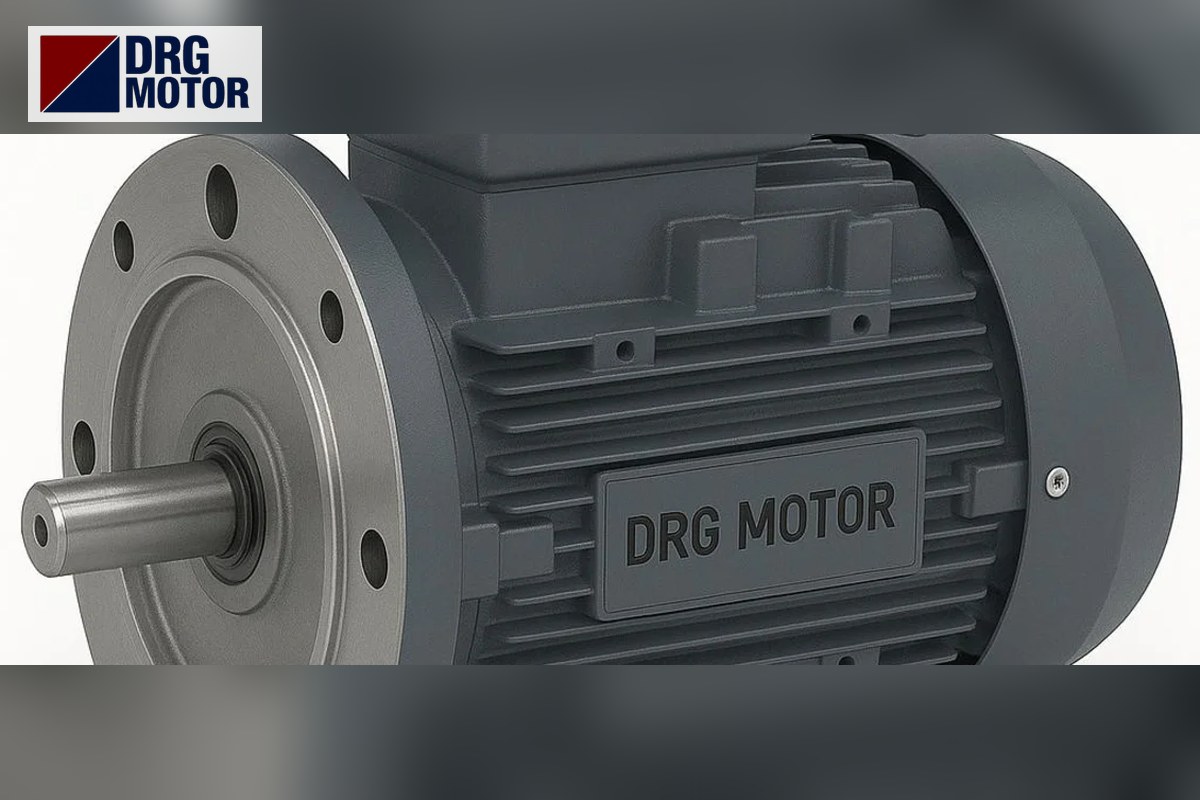

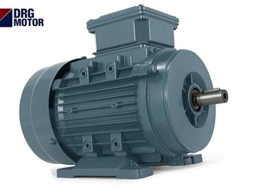
A B35 foot and flange motor carries both B3 feet under its housing and a large B5 flange on its front end shield; the flange centres the motor on the machine axis while the feet transfer weight and vibration to the base frame. B35 is the right choice when the motor must be bolted by its flange to a mating part (pump, gearbox, bell housing) and its weight must not be carried by that joint. There is no separate B35 model: the motor of the same frame, power and speed is ordered with B35 mounting, and its price follows from these technical choices. You can see current prices model by model on the Buy Electric Motors Online page and write the B35 option in the order note.
A B35 drawing combines two families of dimensions: A, B, C, H and K on the foot side, and P, M, N, S, T and LA on the flange side. In this article we merge the two tables on a frame 160L motor to show how to read them, then calculate frame by frame where the flange sits relative to the foot plane.
We covered the cost side of the B3 versus B35 choice in B3 vs B35 and how to write mounting codes on an order in our B3, B5 and B35 ordering guide; here we focus on reading dimensions and the decision criteria.
When should you choose B35?
- A heavy motor bolted by its flange but lying horizontally: On large frames the motor's weight puts shear and bending load on the flange bolts. The feet take this load to the base, and the flange only handles centring and reaction torque.
- When the mating part cannot carry weight: Parts such as an aluminium bell housing or a thin-walled pump casing are not rigid enough to hold the motor suspended.
- Vibrating drives: On crushers, screens and mixers the foot connection limits loosening of the flange bolts.
- Long shaft lines: The motor–coupling–pump group should sit on a common base, and the motor should be supported by its feet during service.
On small frames, when the motor runs vertically, or when the mating part is a sturdy cast gearbox, B5 is usually enough; if the feet will not be used, B35 only adds mounting difficulty.
Foot and flange dimensions together on frame 160L
The table below gives the B3 foot dimensions of the DRG-160L-4 (15 kW, 4-pole) model and the B5 flange dimensions of frame 160L in a single table. Values are taken from the DRG catalogue tables.
| Dimension | Meaning | Value (mm) | Which surface does it tie? |
|---|---|---|---|
| A | Foot hole spacing (across) | 254 | Feet (B3 side) |
| B | Foot hole spacing (along) | 254 | Feet (B3 side) |
| C | Shaft shoulder – first foot hole | 108 | Feet (B3 side) |
| H | Base – shaft axis | 160 | Feet (B3 side) |
| K | Foot holes | 4–Ø14.5 | Feet (B3 side) |
| P | Flange outer diameter | 350 | Flange (B5 side) |
| M | Bolt circle | 300 | Flange (B5 side) |
| N | Spigot diameter | 250 | Flange (B5 side) |
| S | Flange hole diameter | 18.5 | Flange (B5 side) |
| T | Spigot length | 5 | Flange (B5 side) |
| LA | Flange thickness | 15 | Flange (B5 side) |
| D×E | Shaft diameter × length | 42×110 | Shaft |
| L | Overall length | 652 | Shaft |
Both dimension families describe the same axis
On a B35 the position of the shaft axis is defined twice: on the foot side by the base-to-axis height H = 160 mm, and on the flange side by the 250 mm spigot. The height difference between the foot surface on the base and the spigot recess of the mating part must therefore also be exactly 160 mm. If it is not, either the flange is strained or the feet are left floating. The correct sequence is: seat the flange first and tighten its bolts, then measure the gap under the feet and fill it with shims, and tighten the foot bolts last. Tightening the feet first and then pulling the flange in with bolts stresses the housing.
Does the flange extend below the foot plane? Check by frame
A point often missed on B35 is that the flange outer diameter can be larger than the shaft height. If the flange radius (P/2) exceeds the shaft height (H), the lower edge of the flange drops below the foot plane, and the base frame needs a gap or step in that area. The values below are calculated from the P and H dimensions in the catalogue.
| Frame | Shaft height H (mm) | Flange outer diameter P (mm) | P/2 − H (mm) | Does the flange extend below the foot plane? |
|---|---|---|---|---|
| 80 | 80 | 200 | 20 | yes (+20) |
| 90L | 90 | 200 | 10 | yes (+10) |
| 100L | 100 | 250 | 25 | yes (+25) |
| 112M | 112 | 250 | 13 | yes (+13) |
| 132M | 132 | 300 | 18 | yes (+18) |
| 160L | 160 | 350 | 15 | yes (+15) |
| 180L | 180 | 350 | −5 | no |
| 200L | 200 | 400 | 0 | flush |
| 225M | 225 | 450 | 0 | flush |
| 250M | 250 | 550 | 25 | yes (+25) |
| 280M | 280 | 550 | −5 | no |
| 315M | 315 | 660 | 15 | yes (+15) |
For example, on frame 100L the flange drops 25 mm below the foot plane and on frame 250M 25 mm; on frames 200L and 225M the lower edge of the flange is flush with the base. Before placing a B35 motor on a flat plate base, check this table and the dimensioned drawing on our technical drawings page.
Load on the flange bolts: a worked example
To see why the feet help, look at the reaction torque carried by the flange bolts. The DRG-160L-4 has a rated torque of 97.8 Nm and a starting torque ratio Ts/Tn = 2.2. With a bolt circle radius of 150 mm, the total tangential force carried by the bolts is:
- At rated load: 97.8 Nm / 0.15 m ≈ 650 N
- At starting: (97.8 × 2.2 =) 215.2 Nm / 0.15 m ≈ 1430 N
This force alone is not large for the bolts; the main load on a horizontal motor is the bending moment that the housing weight creates on the flange, and it grows as the housing gets longer. On a B35 this bending load goes through the feet to the base, and the flange bolts only take the reaction force above plus the centring. This is an example calculation; for critical applications compare it with the load allowed by the maker of the mating part.
Common mistakes when choosing B35
- Tightening bolts without shimming the feet: If the flange and the foot plane do not bear at the same time, the housing is stressed and the bearings wear early.
- Forgetting that the flange drops below the base: A motor placed on a flat base rests on its flange and the feet stay in the air.
- Confusing B35 with B34: Feet plus a small flange is B34; B35 has the large flange.
- Deriving the shaft size from the flange: The FF300 flange is paired with a 42×110 mm shaft on 160L and a 48×110 mm shaft on 180L; the full list of B5 flanges is in our B5 motor flange dimensions table.
Technical factors that set the price of a B35 motor
- Frame and power: As the frame grows, foot and flange dimensions and the shaft grow too.
- Pole number: A lower speed means a larger frame at the same power.
- Housing material: Motors of 15 kW and above have cast iron housings; aluminium is also available at smaller powers.
- Mounting code and options: B35, B5 or B3; extras such as PTC/PT100 thermal protection.
To compare these factors, browse the 120 models in our online store and add a "B35" note to the order of the model you choose.
B35 ordering and installation checklist
- Were the spigot diameter N and bolt circle M of the mating part measured?
- Do the foot holes on the base match the A × B spacing and the K hole size?
- Is the height between the foot surface and the spigot axis equal to H?
- If the flange drops below the foot plane, has a gap been left in the base?
- Is the sequence flange first, shims next, foot bolts last written into the installation instructions?
- Motors of 4 kW and above are wound 400/690 V; have delta connection and the starting method been planned for a 380 V supply?
Cast iron motors you can order with B35 mounting
- DRG-112M-4 – 4 kW – 1450 rpm – 112M frame (feet A×B 190×140 mm, H 112 mm)
- DRG-160L-4 – 15 kW – 1465 rpm – 160L frame (feet A×B 254×254 mm, H 160 mm)
- DRG-180L-4 – 22 kW – 1470 rpm – 180L frame (feet A×B 279×279 mm, H 180 mm)
- DRG-225M-4 – 45 kW – 1485 rpm – 225M frame (feet A×B 356×311 mm, H 225 mm)
- DRG-250M-4 – 55 kW – 1485 rpm – 250M frame (feet A×B 406×349 mm, H 250 mm)
- DRG-280S-4 – 75 kW – 1486 rpm – 280S frame (feet A×B 457×368 mm, H 280 mm)
Click to see current prices and order these motors nowSEE PRICES →
Frequently Asked Questions
What does B35 motor mean?
B35 is the mounting type in which B3 feet and a B5 flange are on the same motor. The motor can be fixed to a base by its feet and to a mating part by its flange.
Is the flange of a B35 motor the same size as a B5?
Yes, on the same frame the B35 flange has the same dimensions as the B5 flange. The only difference is the feet under the housing.
Is it acceptable to use only the feet of a B35 motor?
It is possible; without the flange the motor works like a B3. Check, however, that the flange edge does not touch the base, especially on frames where P/2 is larger than H.
Can a B35 motor be mounted vertically?
Vertical mounting uses the flange-mounted V1 (shaft down) arrangement; the feet have no function in that position. If vertical operation is required, state it separately on the order.
All models suitable for B35 mounting are listed on the Buy Electric Motors Online page. Send your base and mating part dimensions to [email protected] or call +90 (542) 666 11 11; other channels are on our contact page. DRG Motor is an electric motor manufacturer and supplier.