English
 Le français
 Türkçe




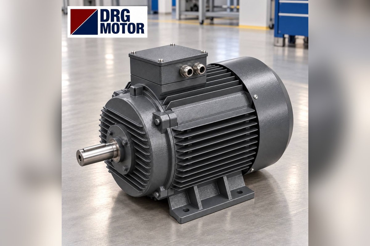

A foot-mounted motor can replace a flange motor only when the flange is used purely as a support: if the motor shaft is connected to the driven machine through a flexible coupling and a rigid, adjustable base can be built under the motor, a B3 foot-mounted motor will do the job. If the flange also performs centring, that is, if the shaft axis is set by the flange spigot on a bell-housing pump, a gearbox input or a gear unit, a foot-mounted motor is the wrong answer; in that case buy the same flange motor (B5) or a B35 motor with both feet and flange.
The deciding factor is not power or speed but where the motor is held on the machine. B3, B5 and B35 motors of the same kW and speed have identical electrical data; only the mechanical mounting changes. Before removing the motor, switch off at the panel and lock out the fuse; leave cable removal and the terminal connection of the new motor to a qualified electrician.
DRG Motor is a manufacturer, supplier and seller of electric motors. You can filter all foot and flange models by power and speed among the 120 models on our Buy Electric Motors Online page; this article explains, step by step, what to check when moving from one mounting type to another.
How is a flange motor fixed to the machine, and how is a foot motor?
A B5 large-flange motor is bolted to the machine through the flange on its front end shield. The spigot in the middle of the flange (diameter N) enters the recess in the mating part and fixes the shaft axis to within fractions of a millimetre. In this arrangement the flange also carries the motor weight; there is usually no support under the motor at all.
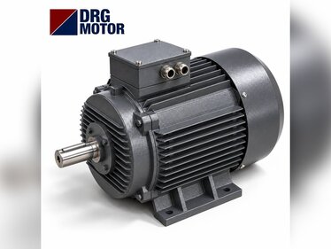
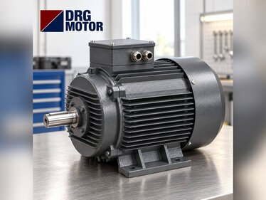
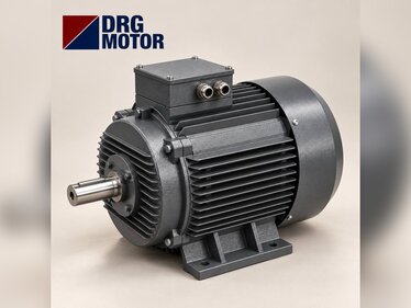
On a B3 foot-mounted motor the axis height is set by dimension H, from the underside of the feet to the shaft centre. The motor is bolted to a frame or base with four foot bolts; keeping the shaft on the same axis as the driven machine depends on base height and thin adjustment plates (shims). In other words, with a flange motor the parts give you the alignment, with a foot motor the fitter creates it.
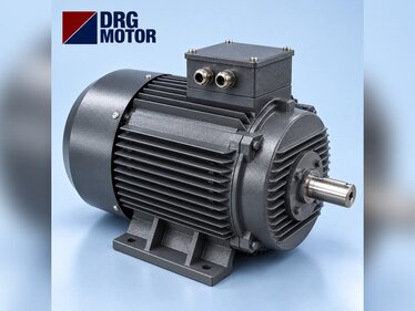
B35 combines the two: the feet carry the weight and the flange centres the shaft. For many users thinking of a foot motor instead of a flange motor, it is also the option that works with the fewest changes; details are in the decision table below.
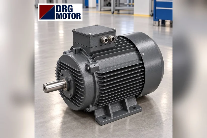
Decision table: when does a foot motor work, and when not?
Read the table against your existing machine. Whichever row on the left matches your installation, the option on the right is recommended.
| Existing connection | Will foot (B3) work? | Recommended |
|---|---|---|
| Flange + flexible coupling, no support | Yes, with a base | B3 + base or B35 |
| Bell-housing pump set | No | B5 or B35 |
| Gearbox input flange | No | Same flange motor |
| Hanging on flange, vertical | No | Flange motor |
| Flange + belt and pulley | Yes, with slide rails | B3 + slide rails |
| Flange size unknown | Measure first | Decide on measurements |
What the “no” rows have in common is that the driven side relies on the motor’s own bearings and flange for alignment. In a bell-housing pump the pump shaft and motor shaft meet through a coupling inside the bell, and only the centring recesses at both ends of the bell keep the two shafts on one axis. “Bringing” a foot motor up to that bell with foot bolts means forcing two shafts into line.
Why is the flange spigot diameter so critical?
Two flange dimensions are often confused: the pitch circle M tells you the diameter on which the bolts sit; the spigot diameter N is the diameter of the pilot ring protruding from the flange. The bolts clamp the flange, but N sets the axis. In the DRG catalogue the B5 spigot length T is 4 mm on frame 112M and 5 mm on frame 160M; this short ring is what seats the motor exactly in the mating recess.
When you switch to a foot motor, this centring disappears. Misalignment comes back as extra bearing load, early wear of the coupling insert, oil seal leakage and vibration. The misalignment a coupling can accept is the coupling maker’s data; do not commission the machine before checking alignment against that value with a dial indicator or a laser alignment tool.
Example: same flange, different shaft height
In the DRG catalogue frames 100L and 112M use the same B5 flange: outside diameter P 250 mm, pitch circle M 215 mm, spigot N 180 mm, shaft 28×60 mm. With a flange connection both motors seat on the machine in the same way. In the foot versions, however, the shaft heights differ: H is 100 mm on frame 100L and 112 mm on frame 112M. That is why the assumption “the flange was the same, so the feet will fit too” is wrong when going from flange to foot.
Click to see current electric motor prices and order nowSEE PRICES →
How do you work out coupling alignment and base height for a foot motor?
When fitting a foot motor in place of a flange motor, the first job is to measure the height of the driven machine’s shaft axis above the surface where the motor will sit. Call this value X. The required base (or packing plate) thickness is simply:
Base thickness = X − H
Assumption: the driven machine’s shaft axis is 150 mm above the frame surface where the motor will be placed. A foot motor in frame 112M has H 112 mm, so a 38 mm base is needed; in frame 132S H is 132 mm, so 18 mm is enough. If X turns out smaller than H, the foot motor will not fit on that frame; the frame must be machined or a smaller frame used.
The base gives the rough alignment; the final adjustment is made with shims. It is therefore much easier to make the base slightly thinner than calculated and make up the difference with shims than to grind down a base that is too thick. Use the catalogue dimensions for the foot holes: on frame 112M the foot hole spacing A×B is 190×140 mm with 12 mm holes; on frame 132S 216×140 mm; on frame 132M 216×178 mm. Drilling the base to these dimensions and fixing the motor with slotted holes leaves room for fine adjustment of coupling alignment. For coupling alignment details, see our article on shaft and coupling alignment.
Base, adapter plate or B35: three ways to switch
1. Foot motor + base
This is the simplest solution if the driven machine does not centre the motor by its flange. The base is made from steel plate or sections, must be rigid enough to carry vibration, and must be welded or bolted to the frame. A thin, flexing sheet base will lose alignment at the first start.
2. Using the old flange seat with an adapter plate
On some machines the face where the motor flange was bolted is kept, and an angle bracket or adapter carrying the foot motor is fitted in between. Centring then depends on the workmanship of the adapter; an adapter made without turning will not give the precision the flange provided.
3. Moving to a B35 motor
If the complaint is the weight or vibration of a flange motor, choosing a B35 motor with both feet and flange is often the most sensible route instead of switching to a foot motor: the flange keeps the centring and the feet transfer the load to the frame. How to read B35 dimensions is explained in our B35 foot and flange motor article.
The table below summarises, from the B5 flange dimensions in the DRG catalogue, the four frames most often met in such a changeover. Compare your existing flange with these values to confirm your motor’s frame.
| Frame | P / M / N (mm) | Hole S (mm) | Shaft D×E (mm) |
|---|---|---|---|
| 90L | 200 / 165 / 130 | 12 | 24×50 |
| 112M | 250 / 215 / 180 | 14.5 | 28×60 |
| 132S / 132M | 300 / 265 / 230 | 14.5 | 38×80 |
| 160M / 160L | 350 / 300 / 250 | 18.5 | 42×110 |
Drawings for all frames are on our technical drawings page.
When must you definitely stay with a flange motor?
- Bell-housing pump and hydraulic power unit: the pump shaft is centred by the motor flange; a foot motor strains the pump bearings and gland.
- Gearbox input: the motor shaft enters the gearbox input bore or coupling seat; this connection cannot be made without flange centring.
- Vertical mounting: if the motor hangs from its flange facing up or down, feet are useless; the flange motor is chosen for that position.
- Motor enclosed in a machine housing: if there is no room for a foot motor, a base cannot be built.
- Moving carrier: if the motor is carried by its flange on a slide or arm, a foot motor will work loose later.
Checklist before the changeover
- Have power, speed and voltage been noted from the old motor’s nameplate?
- Has the flange type been identified: large flange with through holes (B5) or small flange with tapped holes?
- Does the flange centre the shaft, or is it only a bolted joint?
- Has the driven shaft height X been measured and the base thickness X − H calculated?
- Are the coupling type and its permissible misalignment known?
- Are shaft diameter D and length E the same as the old motor; does the coupling hub fit the new shaft?
- Do the terminal box orientation and cable length suit the new position?
- Will direction of rotation be checked uncoupled before commissioning?
Motors in this power range
When switching from flange to foot on pumps, fans and coupled drives, the most frequently asked powers are 3–11 kW. The cast-iron 1500 rpm models below are a starting point for both a foot motor on a base and a B35 changeover:
| Model | Power / speed | Frame | Current 400 V |
|---|---|---|---|
| DRG-100L2-4 | 3 kW / 1450 rpm | 100L cast iron | 6.02 A |
| DRG-112M-4 | 4 kW / 1450 rpm | 112M cast iron | 7.95 A |
| DRG-132S-4 | 5.5 kW / 1460 rpm | 132S cast iron | 10.7 A |
| DRG-132M-4 | 7.5 kW / 1460 rpm | 132M cast iron | 14.3 A |
| DRG-160M-4 | 11 kW / 1465 rpm | 160M cast iron | 20.4 A |
- DRG-100L2-4 – 3 kW – 1450 rpm – 100L cast iron
- DRG-112M-4 – 4 kW – 1450 rpm – 112M cast iron
- DRG-132S-4 – 5.5 kW – 1460 rpm – 132S cast iron
- DRG-132M-4 – 7.5 kW – 1460 rpm – 132M cast iron
- DRG-160M-4 – 11 kW – 1465 rpm – 160M cast iron
Click to see current prices and order these motors nowSEE PRICES →
Frequently Asked Questions
Can a B3 motor replace a B5 motor?
Yes, if the motor flange is only a support and the shaft is connected through a flexible coupling; a base is built for the foot motor and alignment is set with shims. If the flange performs centring (bell-housing pump, gearbox), it cannot.
Is there an electrical difference between a flange motor and a foot motor?
B3, B5 and B35 motors of the same power, speed and frame have the same current, torque and connection data. The difference is purely mechanical; nothing needs changing in the panel.
Can a flange be added to a foot motor later?
It is possible on frames whose front end shield can be swapped for a flanged shield, but the shield must match the frame and centring accuracy must be preserved. Ordering B5 or B35 directly is safer.
How do I measure the flange?
Measure the flange outside diameter P, the bolt pitch circle M and the spigot diameter N with a calliper; note the hole diameter and number of holes. Compare these values with the frame table to identify the motor frame.
You can send your measurements or a nameplate photo to +90 (542) 666 11 11 or [email protected]; all channels are on our contact page. For the current list of foot, flange and B35 models, see the 120 models in our online store.