English
 Le français
 Türkçe




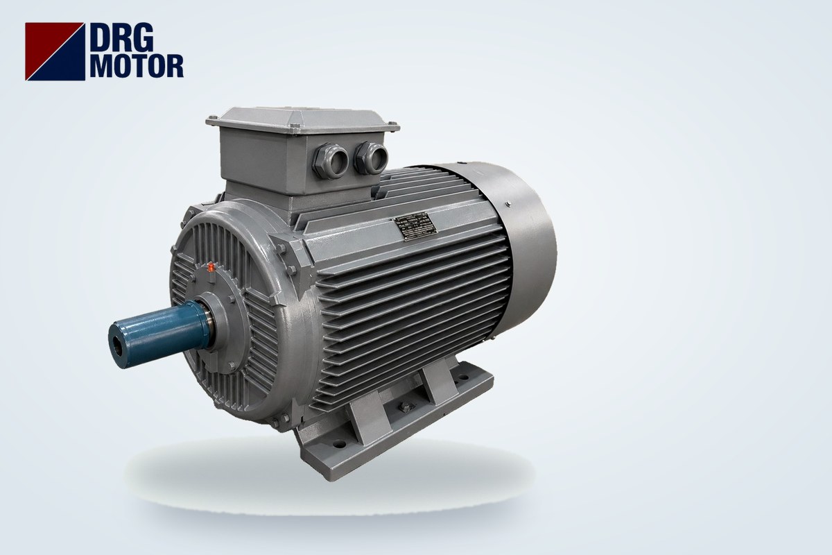

A three-phase induction motor running at no load, with nothing coupled to its shaft, still draws a noticeable share of its rated current (In); most of that current is magnetising current that does no mechanical work. There is no single “correct” no-load percentage: in small and multi-pole motors the no-load current is a large fraction of In, in large motors it is smaller. Example: the 37 kW, 1500 rpm DRG-225S-4 draws 69.6 A at full load on 380 V with a cos φ of 0.86; the reactive (magnetising-side) component of that current works out to about 35.5 A. Seeing a value somewhat below this on the clamp meter, nearly equal on all three phases, is normal at no load. The exact no-load current comes from the motor data sheet or your own measurement.
No-load current is not a fault symptom; it is the price the motor pays to build its magnetic field. The warning signs are a current approaching the rated current, a clear difference between phases, a motor that heats up while idling or a change in its sound. Below we use real data to explain where no-load current comes from, how to measure it, how it changes as load is applied and where to look when it is too high. To compare nameplate values, every product on the Buy Electric Motors Online page lists the 380, 400 and 415 V current together with cos φ.
Why does a motor draw current at no load?
No current is fed to the rotor of an induction motor from outside; the rotor current is induced by the rotating magnetic field created by the stator. To build that field, the stator must continuously draw current from the supply. Because this current lags the voltage by 90°, it is reactive: it oscillates between the supply and the motor and is not delivered to the shaft as power. Whether the motor is idling or fully loaded, the field has to exist, which is why no-load current never drops to zero.
A small part of the no-load current is active current covering real losses: resistive loss in the stator winding, hysteresis and eddy-current losses in the iron core, bearing friction and the power the fan needs to move air. Since these losses are small, the no-load cos φ is very low; the current may look high while the active power actually drawn is small. A clamp meter reading is the vector sum of the active and reactive components, so the current value alone does not tell you how much energy the motor uses.
Small vs large motors: why the ratio to In differs
The air gap between stator and rotor is the main factor setting the magnetising current; air resists magnetic flux far more than iron. In small motors the air gap is larger relative to the machine size, so the current needed to build the field takes a bigger share of the rated current. As power rises, this share shrinks and full-load cos φ increases.
Our data does not contain a separate no-load current column, so the table below does not show no-load current but the reactive component of the full-load current (I·sin φ). The actual no-load current is somewhat lower, yet the table correctly shows how the ratio changes with power. Values are calculated from the nameplate data of 4-pole (1500 rpm) store models.
| Model | Power | Speed (rpm) | In at 380 V (A) | cos φ | I·sin φ (A, calculated) | I·sin φ / In |
|---|---|---|---|---|---|---|
| DRG-802-4 | 0.75 kW | 1420 | 1.84 | 0.75 | 1.2 | 66% |
| DRG-112M-4 | 4 kW | 1450 | 8.37 | 0.82 | 4.8 | 57% |
| DRG-160M-4 | 11 kW | 1465 | 21.5 | 0.85 | 11.3 | 53% |
| DRG-225S-4 | 37 kW | 1485 | 69.6 | 0.86 | 35.5 | 51% |
| DRG-315S-4 | 110 kW | 1488 | 197 | 0.89 | 89.8 | 46% |
How to read it: in the 0.75 kW motor roughly two thirds of the full-load current is reactive, so a no-load reading fairly close to the rated current is not surprising. In the 110 kW motor the reactive share falls below one half. At the same power, the share grows with the number of poles: at 37 kW, I·sin φ is about 30.7 A for the 2-pole DRG-200L2-2, 35.5 A for the 4-pole DRG-225S-4 and 38.9 A for the 6-pole DRG-250M-6. This is why rules that answer “what percentage of In should no-load current be” with a single number create needless fault suspicion on small and multi-pole motors.
37 kW example: how current and cos φ change with load
To see how current varies with load, take the nameplate values of the DRG-225S-4: In = 69.6 A, cos φ = 0.86. At full load the active component is 69.6 × 0.86 ≈ 59.9 A and the reactive component 69.6 × 0.51 ≈ 35.5 A. In a simplified model where the reactive component is constant and the active component is proportional to load, total current and cos φ change as follows:
| Load | Active component (A) | Total current (A) | cos φ (calculated) |
|---|---|---|---|
| 25% | 15.0 | 38.5 | 0.39 |
| 50% | 29.9 | 46.4 | 0.64 |
| 75% | 44.9 | 57.2 | 0.78 |
| 100% | 59.9 | 69.6 | 0.86 |
This is an approximate model; in reality the leakage reactance share also grows with load, so the current at no load and light load is slightly lower than calculated. Two conclusions nonetheless always hold on site. First, when the load halves the current does not halve; the 37 kW motor still draws around two thirds of its rated current at half load. Second, cos φ falls quickly at light load, so running a large motor permanently underloaded is also a disadvantage on the reactive-energy side. Starting, however, needs high current regardless of load: with an Is/In ratio of 7.4, this motor's direct-on-line inrush is about 515 A; at no load only the duration gets shorter. Currents of the same power class with star-delta starting are covered separately in How Many Amps Do 37 and 45 kW Motors Draw?
How to measure no-load current, step by step
A no-load current test is the simplest health check before installing a motor or when a fault is suspected. Because it is done on live equipment, it must be carried out by a qualified electrician using proper protective equipment.
- Disconnect the load. Remove the coupling or take off the belts. A reading with belts fitted is not “no load”; belt tension raises the current.
- Check the connection against the nameplate. A 230/400 V motor is connected in star on a 380–400 V supply, a 400/690 V motor in delta. Correct links directly affect no-load current (see Motor Terminal Star and Delta Connection).
- Measure the supply voltage. Record all three line-to-line voltages. A supply above the rated voltage raises no-load current markedly; interpret the reading together with the voltage.
- Run the motor for a few minutes. Start reading after the inrush has died away and speed has settled.
- Measure each phase separately. Clamp a single phase conductor each time. Note the three values and their average.
- Calculate the imbalance. Divide the largest deviation from the average by the average and multiply by 100. Even a small voltage imbalance appears amplified in no-load current, so check voltage balance first.
- Keep a record. Write the no-load current and voltage measured on a new motor in the maintenance log. Comparing later readings taken under the same conditions is a far more reliable fault indicator than any single percentage rule.
Possible causes of high no-load current
High voltage or voltage not matching the nameplate
Magnetising current does not rise linearly with voltage; as the core approaches saturation, a small voltage increase raises current disproportionately. A motor supplied near the top of its rated range may show clearly higher no-load current and feel warm while idling. Check line-to-line voltages first.
Wrong star/delta connection
If a 230/400 V motor is mistakenly connected in delta on a 380–400 V supply, each winding sees about √3 times its design voltage; no-load current rises sharply, the motor hums and soon overheats. In the opposite case, a 400/690 V motor connected in star on 400 V shows low no-load current but cannot carry its torque under load, and its current climbs. A low no-load current does not always mean “good”.
Mechanical friction and bearings
A worn or wrongly greased bearing, a rubbing fan cover or misaligned mounting increases the active part of the no-load current. Sound and temperature then change along with the current; see How to Tell Motor Bearing Failure for the symptoms.
Air gap and rewinding changes
In a motor with worn bearing housings or an eccentric rotor the air gap becomes uneven, increasing magnetising current and the difference between phases. If a previously rewound motor has a different number of turns from the original, its no-load current will deviate clearly from what the nameplate data of the same model suggests.
Phase loss and imbalance
A motor running at no load can keep turning even if one phase is lost; the current in the remaining two phases then rises and the motor hums. One phase reading zero or very different from the others calls for a check of the connections, contactor contacts or fuses.
Can the load be estimated from no-load current?
Only partly. The 37 kW table above shows that in the light-load region current changes very little with load: the difference between quarter-load current and no-load current is small because the reactive component dominates. So the reading “current is half the nameplate, so the motor is at half load” is wrong. To see the load ratio realistically, use a power analyser that measures cos φ or active power alongside current. Near rated load, on the other hand, current is a good indicator; as the clamp reading approaches In, the motor really is approaching full load. To compare rated currents across powers and voltages use the Motor Current Chart, and for other calculations the Electric Motor Calculators page.
No-load current checklist
- Is the coupling or belt disconnected and does the shaft turn freely by hand?
- Do the nameplate voltage (230/400 V or 400/690 V) and the terminal links suit the supply?
- Are the three line-to-line voltages within the rated range and close to each other?
- Was current read a few minutes after starting, once speed had settled?
- Were all three phases measured separately and the imbalance percentage calculated?
- Is the reading around or below the reactive component of full-load current (In × sin φ)?
- Does the motor stay cool at no load, without humming or knocking?
- Was the value compared with an earlier measurement on the same motor?
Motors in this power range
Models used in the calculations of this article; each product page lists 380/400/415 V current, cos φ, Is/In and bearing data:
- DRG-802-4 – 0.75 kW – 1500 rpm – aluminium
- DRG-112M-4 – 4 kW – 1500 rpm – aluminium
- DRG-160M-4 – 11 kW – 1500 rpm – aluminium
- DRG-200L2-2 – 37 kW – 3000 rpm – cast iron
- DRG-225S-4 – 37 kW – 1500 rpm – cast iron
- DRG-250M-6 – 37 kW – 1000 rpm – cast iron
- DRG-315S-4 – 110 kW – 1500 rpm – cast iron
Click to see current prices and order these motors nowSEE PRICES →
Frequently Asked Questions
How many amps does a 4 kW motor draw at no load?
The 4 kW, 1500 rpm DRG-112M-4 draws 8.37 A at full load on 380 V with a cos φ of 0.82; the reactive component of the full-load current is about 4.8 A. Seeing somewhat less than this at no load, nearly equal on all three phases, is normal. The exact no-load current is taken from the data sheet or a measurement.
No-load current differs between phases — is that normal?
Small differences are normal; no-load current is very sensitive to voltage imbalance. Measure the three line-to-line voltages first. If one phase still differs clearly while the voltage is balanced, check connections, contactor contacts, the winding or the air gap.
Why does a motor heat up at no load?
Active power is small at no load, so a motor normally only gets slightly warm. Noticeable heating points to voltage above the nameplate, a wrong star/delta connection, bearing friction or a fan that is not cooling (blocked fan cover, low speed on a drive).
No-load current is high but load current is normal — why?
With a high supply voltage the motor approaches saturation at no load and magnetising current rises; once loaded, the active component grows and total current looks close to the nameplate. Check voltage and connection, and compare with your measurement history.
For questions about motor selection or nameplate values, call +90 (542) 666 11 11, email [email protected] or use our contact page. To see every model with its technical data, browse the 120 models in our online store.