English
 Le français
 Türkçe




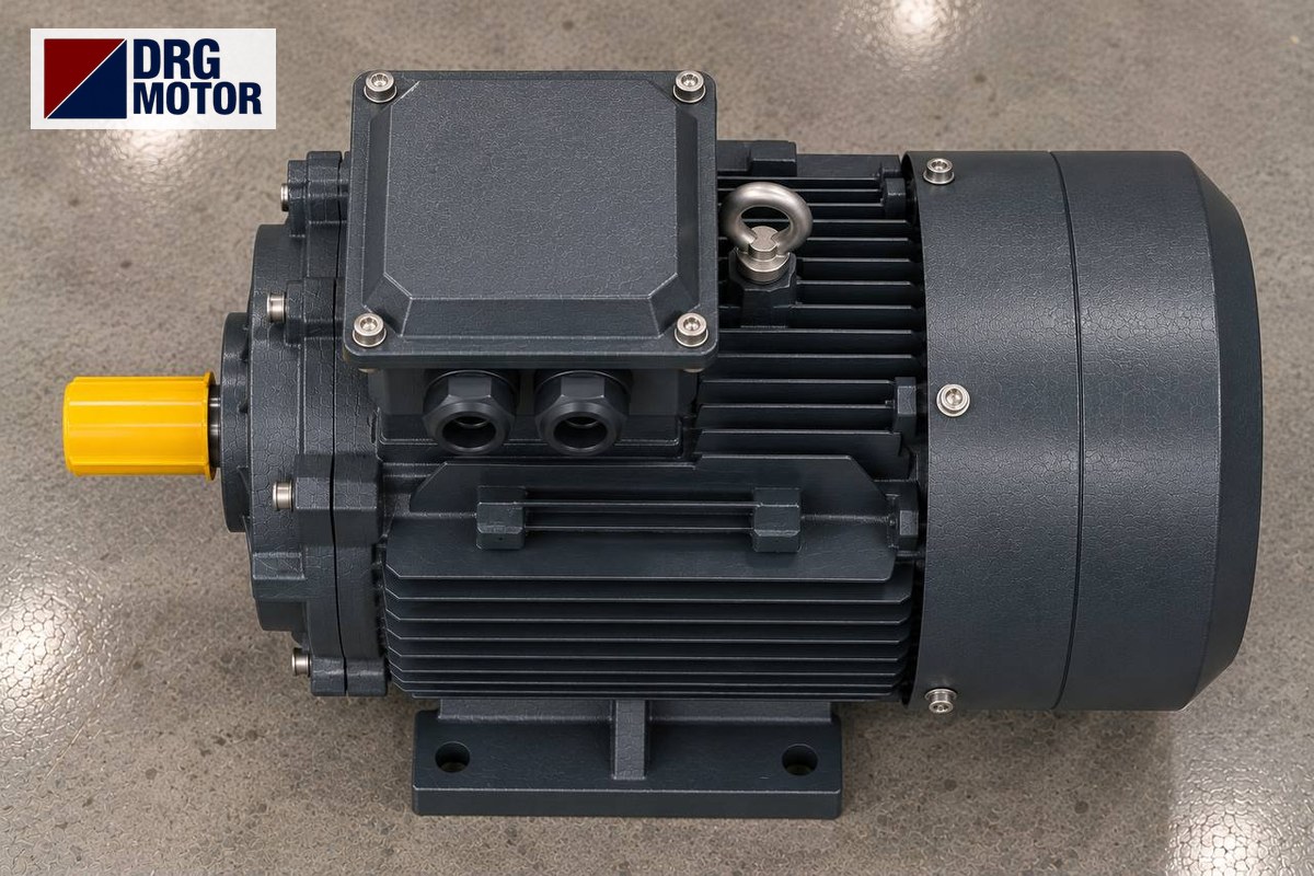

A hammer mill motor is a 2-pole (3000 rpm class) three-phase motor that turns the heavy hammer rotor either direct-coupled or by belt, and what decides the selection is not only the kW rating but the starting time that the rotor inertia (J) imposes on the motor. Example: the 30 kW DRG-200L1-2 delivers 96.8 Nm at a rated speed of 2960 rpm; it brings a rotor with an assumed J = 3.4 kg·m² up to speed in about 5.9 seconds direct on line and in about 19 seconds in the star stage. Starting time determines the overload relay, the timer setting and how hot the motor gets.
Machine power (how many kW, how many tonnes per hour) and hammer tip speed are covered in our article Feed Grinder and Feed Mixer Motor: How Many kW and What Speed?; this article does not repeat them. Here we deal with the physics of starting: estimating inertia, run-up time, the heat released in the rotor at every start, the star-delta changeover moment and shaft matching for direct coupling. You can find suitable models among the 120 models in our online store. Panel, starter and overload settings must be made by a qualified electrician.
Rotor inertia J: what the mill really asks of the motor
The rotor of a hammer mill consists of a disc pack, pins and hammers; it needs little torque to keep turning, but a lot of energy to reach speed. That resistance is the moment of inertia (J, kg·m²). Use the manufacturer’s figure if available; otherwise a rough estimate goes like this (values are examples):
- Hammers: 24 kg in total, radius of rotation 0.24 m → m·r² = 24 × 0.24² ≈ 1.38 kg·m²
- Disc pack: 85 kg, radius 0.22 m, treated as a solid disc → ½·M·R² = 0.5 × 85 × 0.22² ≈ 2.06 kg·m²
- Total: ≈ 3.4 kg·m² (motor rotor and coupling ignored in this example; including them lengthens the time slightly)
With a belt drive, the rotor inertia is referred to the motor shaft by the square of the ratio: Jmotor = Jrotor / i². If the rotor turns slower than the motor, the inertia seen by the motor is smaller. For a general explanation of inertia, see Motor Inertia (J) and Acceleration Time in Motor Selection.
Starting time: worked example of t = J·ω / Tavg
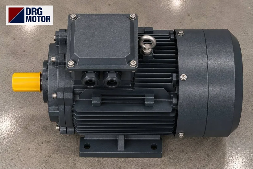
Run-up time is found from the net torque that accelerates the inertia. Motor DRG-200L1-2, direct-coupled, rotor starting empty (feed closed):
- Angular speed: ω = 2π × 2960 / 60 ≈ 310.0 rad/s
- Starting torque: Ts/Tn = 2.0 → 2.0 × 96.8 ≈ 193.6 Nm; breakdown torque Tmax/Tn = 2.3 → ≈ 222.6 Nm
- Conservative assumption for average motor torque: the starting torque, 193.6 Nm (the real curve rises towards Tmax in between, so the time is slightly shorter)
- Assumed windage/friction of the empty rotor: 0.15 × Tn ≈ 14.5 Nm
- Net accelerating torque: 193.6 − 14.5 ≈ 179.1 Nm
- Time: t = 3.4 × 310.0 / 179.1 ≈ 5.9 s
Check: 9550 × 30 / 2960 ≈ 96.8 Nm, the same as the catalogue rated torque. Starting time is proportional to inertia: a rotor twice as heavy takes about twice as long. If the mill starts loaded, load torque rises, net torque falls and the time grows; a hammer mill must always start empty, and the feed should open only after the motor is up to speed.
Heating with direct-on-line starting: J·ω²/2 at every start
When a pure inertia load is accelerated from standstill, the energy released as heat in the rotor is roughly equal to the kinetic energy given to the load. In the example:
- E = ½ · J · ω² = 0.5 × 3.4 × 310.0² ≈ 163 kJ
- Starting current: Is/In = 7.6 → 7.6 × 52.1 A ≈ 396 A, for about 5.9 s
These 163 kJ land on the rotor bars within a few seconds; with back-to-back starts the motor has no time to cool. Practical consequences:
- The overload relay must be of a class able to carry the starting time; if it trips during start, raising the setting above the nameplate current is not the fix — measure the starting time.
- When the screen clogs and the mill stalls, do not restart repeatedly; empty the chamber first and check by hand that the rotor turns freely.
- Ask us or the machine manufacturer for the permissible number of starts per hour, stating the inertia.
Turning the same rotor with the 4-pole DRG-200L-4 (1475 rpm) cuts the starting energy to a quarter (≈ 41 kJ); but tip speed is halved and grinding changes. The pole number is therefore part of the machine’s design and is not changed to make starting easier.
The star-delta changeover: why an 8-second timer is not enough
DRG-200L1-2 is wound for 400/690 V, runs in delta on a 400 V network and is suitable for star-delta starting. In star, current and torque drop to one third:
| Starting method | Starting current | Starting torque | Run-up (example) |
|---|---|---|---|
| Direct on line (DOL) | ≈ 396 A | ≈ 193.6 Nm | ≈ 5.9 s |
| Star (Y) stage | ≈ 132 A | ≈ 64.5 Nm | ≈ 19 s (to 90 % speed) |
In star the net torque is 64.5 − 14.5 ≈ 50.0 Nm; reaching 90 % of rated speed takes t ≈ 3.4 × 0.9 × 310.0 / 50.0 ≈ 19 s. If the timer is set to 8 seconds out of habit, the angular speed at changeover is 50.0 × 8 / 3.4 ≈ 117.7 rad/s, only about 38 % of rated speed. Switching to delta at this speed means drawing almost the full starting current a second time: star-delta is installed but brings no benefit.
- Set the timer to change over once the motor has finished accelerating in star (current has dropped and settled); measure that time with a clamp meter at the first start.
- If the rotor does not accelerate enough in star, load torque is high: check the feed gate, a clogged screen or a jammed hammer.
- To compare methods see motor starting methods and star-delta, and for relay settings the overload relay, fuse and contactor selection tool.
2-pole direct coupling: shaft, coupling and bearings
In a direct-coupled mill, the motor shaft is joined to the rotor shaft by a coupling and both turn at the same speed. On 2-pole motors, in some frames the shaft is thinner than on the 4-pole version of the same frame. DRG catalogue data:
| Frame | 2-pole shaft D×E | 4-pole shaft D×E | 2-pole bearing |
|---|---|---|---|
| 200L | 55 × 110 mm | 55 × 110 mm | 6312-C3 |
| 225M | 55 × 110 mm | 60 × 140 mm | 6313-C3 |
| 250M | 60 × 140 mm | 65 × 140 mm | 6314-C3 |
So when replacing, check the shaft size together with the pole number, even if the frame name is the same: in frame 225M the 2-pole shaft is 55 × 110 mm and the 4-pole shaft 60 × 140 mm, and the coupling hubs do not interchange.
- Coupling alignment: measure radial and angular misalignment with a dial gauge; at high speed even a small offset tires the bearing quickly.
- Balance: when replacing hammers, fit them in opposed weight groups; an unbalanced rotor passes vibration to the motor bearing.
- Reversible operation: some mills reverse rotation to use the other face of the hammers. Direction is changed by swapping two phases; never reverse before the motor has completely stopped.
- Stopping: the heavy rotor coasts for a long time; do not open the cover until it has fully stopped.
Suitable DRG models for hammer mills
The models below are 2-pole with cast iron frames; current values are for 400 V. Choose the model equal to or just above the power on your machine’s nameplate; hammer mill power varies widely with plant capacity, and the exact figure is the machine nameplate.
| Model | Power / speed | Frame | Current 400 V |
|---|---|---|---|
| DRG-160M2-2 | 15 kW / 2945 rpm | 160M cast iron | 26.5 A |
| DRG-160L-2 | 18.5 kW / 2940 rpm | 160L cast iron | 32.5 A |
| DRG-180M-2 | 22 kW / 2955 rpm | 180M cast iron | 38.5 A |
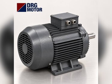
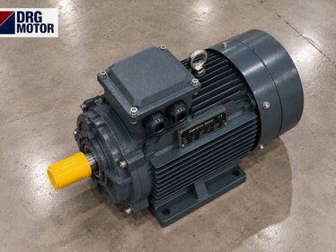
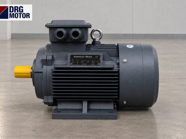
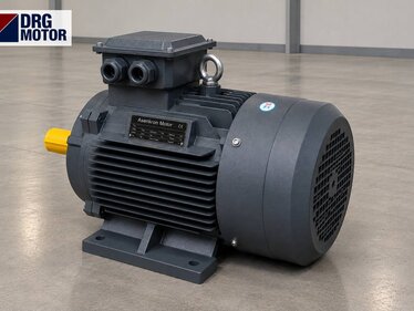
| DRG-200L1-2 | 30 kW / 2960 rpm | 200L cast iron | 52.1 A |
| DRG-200L2-2 | 37 kW / 2960 rpm | 200L cast iron | 64 A |
| DRG-225M-2 | 45 kW / 2965 rpm | 225M cast iron | 76.8 A |
Technical data of the 30 kW model used in the example:
- Power: 30 kW (40 HP)
- Rated speed: 2960 rpm
- Frame: IEC 200L, cast iron
- Current 400 V / 380 V: 52.1 A / 54.9 A
- cos φ: 0.89
- Rated torque: 96.8 Nm
- Ts/Tn · Tmax/Tn: 2 · 2.3
- Is/In: 7.6
- Shaft D×E: 55 × 110 mm
- Voltage: 400/690 V (Δ/Y)
- Bearing: 6312-C3
Motors in this power range
- DRG-160M2-2 – 15 kW – 2945 rpm – 160M cast iron
- DRG-160L-2 – 18.5 kW – 2940 rpm – 160L cast iron
- DRG-180M-2 – 22 kW – 2955 rpm – 180M cast iron
- DRG-200L1-2 – 30 kW – 2960 rpm – 200L cast iron
- DRG-200L2-2 – 37 kW – 2960 rpm – 200L cast iron
- DRG-225M-2 – 45 kW – 2965 rpm – 225M cast iron
Click to see current prices and order these motors nowSEE PRICES →
Frequently Asked Questions
What speed should a hammer mill motor have?
Direct-coupled hammer mills use a 2-pole, 3000 rpm class motor; in the DRG catalogue the rated speed is 2940–2965 rpm between 15 and 45 kW. The pole number belongs to the machine design and must be kept when replacing.
How many amps does a 30 kW motor draw when starting?
For DRG-200L1-2, Is/In = 7.6 and rated current at 400 V is 52.1 A; starting current is about 396 A direct on line and about 132 A in the star stage.
Why does a hammer mill trip the overload relay on star-delta?
Usually the timer is set too short: the changeover to delta happens before the rotor is up to speed in star, and the starting current is drawn a second time. Or the mill is starting loaded. Change over after the current has dropped and open the feed after starting.
How do you find starting time if rotor inertia is unknown?
The most reliable way is to measure: at the first start, time with a stopwatch how long the current takes to fall to its rated value on a clamp meter. For an estimate, add hammer mass × radius² and ½·M·R² for the disc pack, then use t = J·ω/T.
Send us the power, speed, shaft size and mounting details from your machine’s nameplate and we will help you pick the right DRG model: phone +90 (542) 666 11 11, e-mail [email protected], contact page. For all models and ordering, see Buy Electric Motors Online.