English
 Le français
 Türkçe




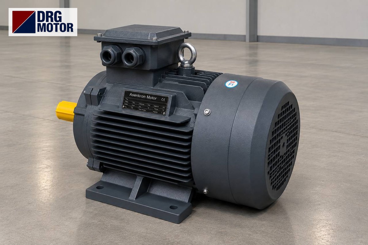

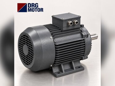
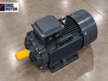
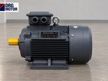
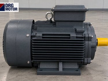
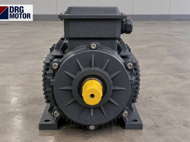
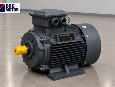
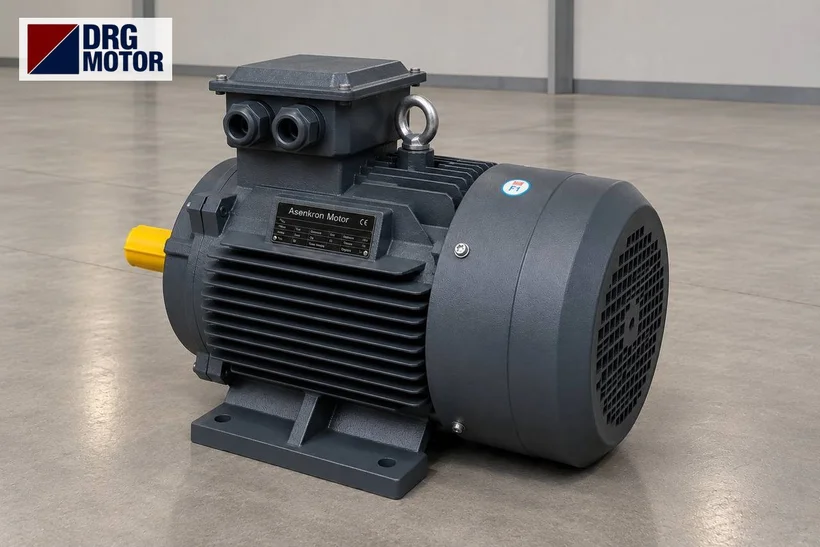
On open two-roll rubber mixing mills, the main drive is usually a 4-pole three-phase induction motor with a synchronous speed of about 1500 rpm, combined with a gearbox that reduces this speed to roll speed. What sizes the motor is the torque required at the roll shaft: for example, the 11 kW DRG-160M-4 delivers 71.7 Nm at its rated speed of 1465 rpm and draws 20.4 A at 400 V; through a gearbox with a ratio of about 81.4, the roll turns at 18 rpm and roughly 5,305 Nm remains at the shaft after the loss allowance. The power per machine depends on roll length, diameter and compound hardness; the exact value is given by the machine nameplate or its builder.
In rubber mixing the load is high-torque, low-speed and shock-loaded, so the motor is selected not by power but by the torque needed at the gearbox output, by peak torque and by starting under load. Below we cover the calculation for open mills and internal rotor mixers, gearbox–coupling matching, starting and emergency stopping, in that order. Motor connection, starting method and the emergency stop circuit must be handled by a qualified electrician. You can find the right frame among the 120 models on our Buy Electric Motors Online page using the power and speed filters.
Open Mill vs Internal Mixer: How the Load Differs for the Motor
On an open mill the two rolls rotate towards each other at slightly different speeds; this speed difference (the friction ratio) shears the rubber in the nip and mixes it. On most machines one motor drives both rolls through the gearbox and friction gears. As the operator cuts and folds the batch, the load fluctuates; when a new batch of cold rubber enters the nip, torque jumps for a short time. The narrower the nip and the harder the compound, the higher the required torque.
In an internal mixer two rotors turn inside a closed chamber while a ram presses the compound onto them. The cycle lasts a few minutes: the ram comes down, fillers and oil are added and torque peaks; as the compound warms up and becomes homogeneous, torque falls, the batch is discharged and the cycle starts again. On this machine the gap between average and peak power is much larger than on an open mill.
Both types share three facts: the load has a constant-torque character (torque demand does not drop with speed), output speed is low, and the machine may remain full after an emergency stop. Motor selection is based on these three facts.
Roll Power Calculation: P = T · n / 9550
If the torque needed at the roll shaft is known, motor power can be calculated directly. This torque comes from the machine builder's data; on an existing machine it can be roughly estimated from the motor current under load and the gearbox ratio. The assumptions in the example below are stated openly: roll torque 4000 Nm, roll speed 18 rpm, roll diameter 0.40 m, and motor power = shaft power × 1.1 to cover gearbox, coupling and bearing losses.
| Step | Formula | Result |
|---|---|---|
| Roll torque | assumption | 4000 Nm |
| Roll speed | assumption | 18 rpm |
| Shaft power | T · n / 9550 | 7.54 kW |
| With loss allowance | × 1.1 | 8.29 kW |
| Selected motor | next standard size | 11 kW, 4-pole |
| Gearbox ratio | 1465 / 18 | 81.4 |
| Output torque | 71.7 × 81.4 / 1.1 | ≈ 5,305 Nm |
The calculation shows a requirement slightly above 8 kW; the next standard size up, 11 kW, is selected. The margin is not wasted: when a cold batch is fed and the nip is closed, torque briefly rises above the rated value. The roll surface speed from v = π · D · n / 60 is 0.38 m/s (about 22.6 m/min); this value directly affects the operator's working pace and the stopping distance in an emergency stop, so the speed specified by the builder should not be exceeded.
If any assumption changes, the result changes too: at the same torque, doubling roll speed doubles the power. The calculation therefore shows an order of magnitude; the machine nameplate or builder data always takes priority.
Gearbox and Coupling Matching: From Motor Shaft to Roll
The gearbox ratio is the motor rated speed divided by roll speed: 1465 / 18 ≈ 81.4. Gearbox output torque equals motor torque × ratio / loss allowance and is around 5,305 Nm in the example. The same output can be obtained with a 6-pole motor: an 11 kW 6-pole motor delivers 108.3 Nm at 970 rpm, the ratio drops to 53.9 and output torque stays the same. The trade-off is a smaller-ratio gearbox against a larger motor frame (160L instead of 160M). The existing gearbox ratio and the space on the base frame decide which one fits; when replacing a motor, keeping the same number of poles as the old one preserves the ratio and roll speed.
There are two ways to connect the motor to the gearbox. In the first, a foot-mounted (B3) motor sits on a common base frame and is connected to the gearbox input shaft with a flexible coupling; here shaft alignment determines vibration and bearing life. In the second, a B5 flange motor sits directly on the gearbox input flange via a coupling bell housing. On the 160M frame the shaft end is 42 × 110 mm; the B5 flange has an outer diameter P = 350 mm, spigot diameter N = 250 mm, bolt circle M = 300 mm and hole diameter S = 18.5 mm. The coupling hub is machined to this shaft diameter and key size.
Under shock loads, the coupling and gearbox are sized for the motor's peak torque, not its rated torque. With a breakdown torque ratio Tmax/Tn = 2.3, the 11 kW motor can briefly produce up to about 164.9 Nm; in a jam this torque is multiplied through the gearbox and passed on to the roll. A coupling with a flexible element softens the shocks, and the gearbox is chosen with a service factor suited to shock loading. For a detailed look at service factor and ratio selection see How to Select a Motor Gearbox: Torque, Ratio and Service Factor, and for a quick ratio and output torque check use the Gearbox Output Speed and Torque Calculator.
Power for an Internal Mixer: Estimating from Batch Energy
Because torque varies constantly in an internal rotor mixer, power is estimated from the energy used per batch. Our assumptions: batch 25 kg, specific mixing energy 0.12 kWh/kg (varies with the compound), cycle 4 minutes, and peak load 1.5 times the average.
- Batch energy: 25 × 0.12 = 3 kWh
- Average power: 3 kWh / (4/60 h) = 45 kW
- Peak power: 45 × 1.5 = 67.5 kW
This peak corresponds to the 75 kW standard size. For example, the DRG-280S-4 delivers 482.0 Nm at 1486 rpm and draws 129.0 A at 400 V; with a rotor speed of 40 rpm, the gearbox ratio is about 37.1. On machines of this class rotor speed is often adjusted to suit the compound; a frequency inverter in constant-torque mode is used for this, and motor cooling is assessed separately if long running at low speed is expected. Monitoring motor current is also a common way to detect the end of a batch: current falls as the compound becomes homogeneous.
Starting a Loaded Mill: Why Star-Delta May Not Be Enough
After an emergency stop, rubber stays between the rolls and the machine has to restart under load. The 11 kW motor has a starting torque ratio Ts/Tn = 2.2, so direct-on-line starting torque is about 157.7 Nm. With star-delta starting, torque in the star stage drops to one third: 157.7 / 3 ≈ 52.6 Nm, only 0.73 times rated torque. If the breakaway torque of the load is above rated torque, the motor cannot turn in star or turns very slowly, and a high current surge occurs at the switch to delta.
With direct-on-line starting, current rises by the ratio Is/In = 7.7 to about 157 A; the supply and panel must be suitable for this. Practical solutions: direct-on-line starting if the supply allows; a frequency inverter, which gives torque close to rated torque at low current; or a procedure that opens the nip and clears the batch before starting. A soft starter also lowers torque by lowering voltage, so on its own it is not a solution for a loaded start. To compare methods, see the Motor Starting Methods and Star-Delta page.
Emergency Stop and Braking: Stopping Distance on a Mill
The nip between the two rolls is the point with the highest risk of a hand being drawn in. These machines have an emergency stop bar or trip wire that the operator triggers with the body or hand; the aim is to stop the rolls within a very short distance and, if needed, open the nip with a brief reverse rotation. Cutting the motor supply alone is not enough: because of the inertia of the rolls, gearbox and motor rotor, the machine keeps turning for a while.
A braking method is therefore required: an electromagnetic brake at the rear of the motor, a separate disc brake at the gearbox input, or dynamic braking with a braking resistor in an inverter system. Braking torque must be large enough to stop the load and the rotating masses within the required time. The permitted stopping distance is set by machine safety regulations and the builder's documentation; the machine must not be operated until this value has been measured after installation and periodically thereafter. The brake circuit and emergency stop chain are a job for a qualified electrician.
Model Selection and Rubber Mixer Motor Checklist
The table below shows 4-pole cast iron DRG models in the power range commonly found on open mills and small internal mixers. Currents are for 400 V; the overload relay is set to this value.
| Model | Power / speed | Frame | Current 400 V |
|---|---|---|---|
| DRG-132M-4 | 7.5 kW / 1460 rpm | 132M · cast iron | 14.3 A |
| DRG-160M-4 | 11 kW / 1465 rpm | 160M · cast iron | 20.4 A |
| DRG-160L-4 | 15 kW / 1465 rpm | 160L · cast iron | 27.3 A |
| DRG-180L-4 | 22 kW / 1470 rpm | 180L · cast iron | 39.7 A |
| DRG-200L-4 | 30 kW / 1475 rpm | 200L · cast iron | 53.8 A |
| DRG-280S-4 | 75 kW / 1486 rpm | 280S · cast iron | 129 A |
Technical data of the model selected in the example calculation:
- Power: 11 kW
- Rated speed: 1465 rpm
- Rated torque: 71.7 Nm
- Current 400 V: 20.4 A
- cos φ: 0.85
- Ts/Tn: 2.2
- Tmax/Tn: 2.3
- Is/In: 7.7
- Shaft D×E: 42 × 110 mm
- IEC frame: 160M · cast iron
Check the following before ordering or replacing a motor:
- Torque and speed required at the roll or rotor shaft (builder data or measurement)
- Gearbox ratio = motor speed / output speed; output torque = Tn × ratio / loss allowance
- Coupling and gearbox rated for the motor's peak torque (Tmax/Tn)
- Mounting: foot B3 or flange B5; shaft D × E and key size
- Starting: if starting under load, direct-on-line or an inverter instead of star-delta
- Emergency stop: brake type, braking resistor and measured stopping distance
- Overload relay: set to nameplate current (Overload, Fuse and Contactor Selection)
- Environment: carbon black and talc dust must not clog the fan cover and frame fins; clean regularly
Motors in This Power Range
- DRG-160M-4 – 11 kW – 1465 rpm – 160M cast iron
- DRG-160L-4 – 15 kW – 1465 rpm – 160L cast iron
- DRG-180L-4 – 22 kW – 1470 rpm – 180L cast iron
- DRG-200L-4 – 30 kW – 1475 rpm – 200L cast iron
Click to see current prices and order these motors nowSEE PRICES →
Frequently Asked Questions
What size motor does a rubber mill need?
It depends on roll length, diameter and compound; the exact value is the machine nameplate. The calculation needs roll torque and speed: assuming 4000 Nm and 18 rpm, shaft power is 7.54 kW, 8.29 kW with the loss allowance, and an 11 kW motor is selected.
How many amps does an 11 kW 4-pole motor draw?
At full load the DRG-160M-4 draws 20.4 A at 400 V and 21.5 A at 380 V. With direct-on-line starting, starting current rises to 7.7 times rated current.
Can an inverter be fitted to a rubber mixing machine?
Yes. An inverter in constant-torque mode allows a loaded mill to start at low current and gives adjustable roll speed. If long running at low speed is expected, motor cooling should be planned separately, and a braking resistor if fast stopping is required.
Why is a mill motor usually 4-pole?
A 4-pole motor reaches roll speed with a reasonable gearbox ratio and offers a good balance between frame size and torque. A 6-pole motor gives more torque at the same power and needs a smaller-ratio gearbox, but its frame is larger.
Send us your machine nameplate or gearbox data and we will identify the right DRG model together; for current prices see Buy Electric Motors Online. Phone: +90 (542) 666 11 11 · E-mail: [email protected] · Contact