English
 Le français
 Türkçe




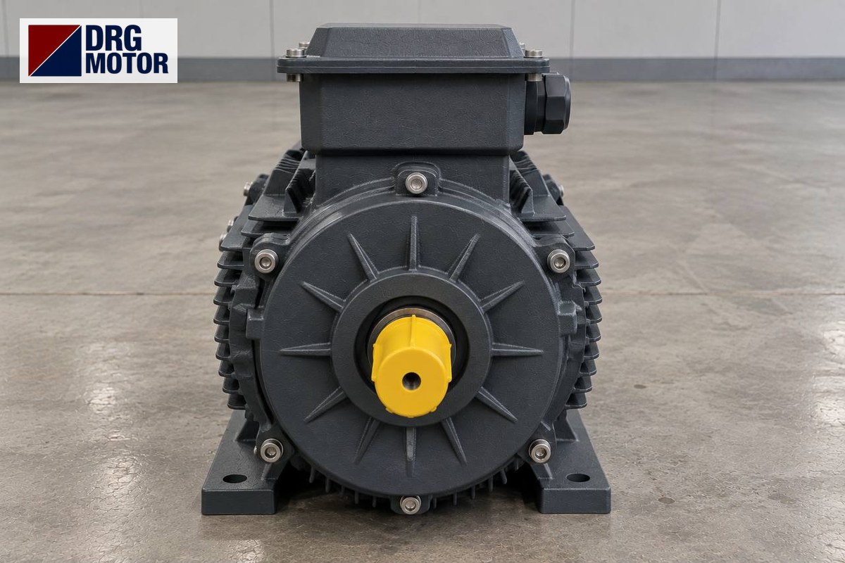

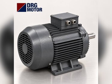
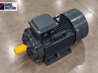
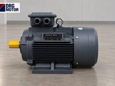
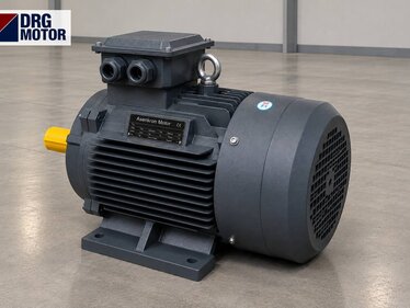
A filter press hydraulic unit motor is usually a 4-pole three-phase motor with a B5 or B35 flange, connected to the pump through a bell housing and a flexible coupling; what decides the selection is the duty pattern rather than the power: within one cycle the motor closes the plates at high flow, then squeezes at high pressure and low flow, and during a long pressure-holding period cuts in and out intermittently. In this article's example, the 7.5 kW 4-pole DRG-132M-4 draws 14.3 A at 400 V, delivers 49.1 Nm rated torque at 1460 rpm and draws 7.5 times rated current, about 107 A, on every direct-on-line start.
So on a filter press two questions must be asked separately: does the motor cover the pump torque at the highest pressure, and do the frequent starts in the holding phase overheat the motor? On the mounting side, flange, shaft and coupling dimensions must match the old motor exactly. You will find all the 4-pole models used on hydraulic units on the Buy Electric Motors Online page. The pressures, displacements and times in this article are example assumptions; the definitive values are on the press and hydraulic unit labels. Panel and motor connection work must be done by a qualified electrician.
How Does the Filter Press Cycle Load the Motor?
A filter press cycle has four phases and the motor load is different in each:
| Cycle phase | Pressure / flow | Motor condition | Watch out for |
|---|---|---|---|
| Closing | Low pressure, high flow | Full speed, medium load | Both pumps deliver |
| Squeezing | High pressure, low flow | Torque at its peak | Large pump unloaded |
| Pressure holding | Pressure steady, flow ~0 | Cuts in intermittently | Starts per hour |
| Opening / release | Low pressure | Short run, then stops | Direction and speed |
Most units have a two-stage (double) pump: the large-displacement pump provides fast movement during closing; as pressure rises an unloading valve dumps it to tank, and the small-displacement pump does the squeezing alone. This arrangement is the main reason the motor can be kept small.
Torque Check: A Double-Pump Example
If the pump displacement and pressure are known, the torque required at the motor shaft can be calculated directly: T = V × p ÷ (20π) (T: Nm, V: cm³/rev, p: bar), then divided by the pump (mechanical) efficiency. A step-by-step kW calculation from flow and pressure is given in Hydraulic Pump Electric Motor Selection: kW Calculation from Pressure and Flow; here we check via torque. Assumptions:
- Large pump 30 cm³/rev, small pump 8 cm³/rev (assumption)
- Closing pressure 50 bar, squeezing pressure 300 bar (assumption)
- Pump (mechanical) efficiency 0.9 (assumption)
- Motor: DRG-132M-4, 1460 rpm, Tn = 49.1 Nm
Closing: both pumps together, (30 + 8) × 50 ÷ 62.83 ≈ 30.2 Nm; with pump efficiency 30.2 ÷ 0.9 ≈ 33.6 Nm. Flow 38 × 1460 ÷ 1000 ≈ 55.5 l/min.
Squeezing: small pump only, 8 × 300 ÷ 62.83 ≈ 38.2 Nm; with pump efficiency ≈ 42.4 Nm. Flow 8 × 1460 ÷ 1000 ≈ 11.7 l/min.
The highest torque demand is 42.4 Nm, below the motor's 49.1 Nm rated torque. At this torque the shaft power is 42.4 × 1460 ÷ 9550 ≈ 6.5 kW; the 7.5 kW motor leaves about 1 kW of margin. If the unloading valve fails and the large pump also tries to deliver at 300 bar, torque rises to (38 × 300 ÷ 62.83 ÷ 0.9) ≈ 202 Nm, exceeding the motor's breakdown torque (49.1 × 2.3 ≈ 113 Nm): the motor stalls and the overload trips. Frequent overload trips often come from this valve, not from the motor.
Catalogue values of the motor in the example:
- Power: 7.5 kW
- Rated speed: 1460 rpm
- Current (400 V): 14.3 A
- cos φ: 0.84
- Rated torque: 49.1 Nm
- Ts/Tn: 2
- Tmax/Tn: 2.3
- Is/In: 7.5
- Shaft (D×E): 38×80 mm
- IEC frame: 132M (cast iron)
Pressure-Holding Phase and Frequent Starts
After squeezing, the plates must stay under pressure. On some units the motor stops and a pressure switch restarts it as pressure falls; on others the motor keeps running and the pump delivers to tank. The first method quickly increases the number of starts. Example assumption: the cycle includes a 45-minute holding time and pressure falls below the threshold every 5 minutes. That means 45 ÷ 5 = 9 starts during holding, about 11 starts per hour including closing and opening.
On every DOL start the DRG-132M-4 briefly draws about 107 A, and the rotor and winding heat faster than normal meanwhile. If the pump is unloaded at start, acceleration is short and the effect is limited; if the pump starts under load (pressure line open, valve not closed), the start lasts longer and heating increases. To assess it:
- Check that the pump is unloaded at start (unloading valve, soft-start valve).
- Reduce the number of starts by widening the pressure switch hysteresis or fixing the leaking valve/seal.
- If very frequent starts are unavoidable, letting the motor idle during holding usually heats it less than continuous stop-start.
- To monitor winding temperature directly, optional PTC / PT100 thermal protection on DRG motors can be specified in the order note.
Star-delta or direct-on-line?
In the DRG catalogue, models of 4 kW and above are wound 400/690 V and connected in delta on a 400 V supply, so they are suitable for star-delta starting; models of 3 kW and below are wound 230/400 V, run in star at 400 V and cannot be star-delta started. With the pump unloaded the starting load is low and star-delta causes no problem; however, the star-to-delta transition creates a short current surge and many transitions per hour wear the contactors. You can compare the options on the motor starting methods and star-delta page, and see overload and contactor values in the overload, fuse and contactor selection tool.
Mounting Fit: Bell Housing, Coupling and Shaft
On a hydraulic unit the motor is usually mounted on the tank lid or a side bracket via a bell housing (pump–motor adaptor); the motor's B5 flange sits on the top face of the bell and the motor shaft is joined to the pump shaft by a flexible coupling. If the motor stands vertically on the tank (shaft pointing down), this mounting arrangement must be stated clearly in the order. To avoid changing the bell housing, the new motor's flange and shaft dimensions must be identical to the old one's. B5 large-flange dimensions from the DRG catalogue (4-pole):
| IEC frame | Flange P / N / M | Shaft D×E | Hole S |
|---|---|---|---|
| 100L | 250 / 180 / 215 mm | 28×60 mm | 14.5 mm |
| 112M | 250 / 180 / 215 mm | 28×60 mm | 14.5 mm |
| 132S | 300 / 230 / 265 mm | 38×80 mm | 14.5 mm |
| 132M | 300 / 230 / 265 mm | 38×80 mm | 14.5 mm |
| 160M | 350 / 250 / 300 mm | 42×110 mm | 18.5 mm |
| 160L | 350 / 250 / 300 mm | 42×110 mm | 18.5 mm |
The bell housing is machined to the spigot diameter (N); moving from a 132 frame to a 160 frame means changing the bell housing as well. The motor-side coupling hub is chosen by shaft diameter (D) and key width. For full dimensions see the DRG motor technical drawings page.
Motor Replacement Checklist
- Note kW, speed, voltage and connection from the old motor's nameplate; do not go from 4-pole to 2-pole, the pump's permitted speed would be exceeded.
- Are the flange type (B5 / B35), P–N–M dimensions and shaft D×E the same as before?
- Does the coupling hub sit on the shaft with its key and is the set screw tight? Is the coupling element worn or crushed?
- Is the axial gap between motor and pump shafts at the coupling maker's value? The shaft ends must not touch.
- In vertical mounting, are the terminal box and cable entries oriented to protect against oil and water dripping from above?
- On first start, run the motor briefly and compare the direction of rotation with the arrow on the pump body; a pump running backwards is damaged quickly.
- Is the overload set to the rated current on the nameplate (14.3 A at 400 V for the DRG-132M-4)?
Which DRG Motor Should You Choose?
On filter press hydraulic units the motor power varies with press size and pump layout; on small and medium presses it is mostly seen from a few kilowatts up to around 15 kW. The definitive value is the unit's nameplate. The 4-pole cast iron models below cover this range:
| Model | Power / speed | Frame | Current 400 V |
|---|---|---|---|
| DRG-100L1-4 | 2.2 kW / 1450 rpm | 100L cast iron | 4.52 A |
| DRG-100L2-4 | 3 kW / 1450 rpm | 100L cast iron | 6.02 A |
| DRG-112M-4 | 4 kW / 1450 rpm | 112M cast iron | 7.95 A |
| DRG-132S-4 | 5.5 kW / 1460 rpm | 132S cast iron | 10.7 A |
| DRG-132M-4 | 7.5 kW / 1460 rpm | 132M cast iron | 14.3 A |
| DRG-160M-4 | 11 kW / 1465 rpm | 160M cast iron | 20.4 A |
| DRG-160L-4 | 15 kW / 1465 rpm | 160L cast iron | 27.3 A |
When choosing between models, first do the torque check above, then pick the frame that fits the existing bell housing. For example, the 4 kW DRG-112M-4 and the 5.5 kW DRG-132S-4 have different flange sizes (P 250 mm versus 300 mm).
Motors in This Power Range for Filter Press Hydraulic Units
- DRG-100L2-4 – 3 kW – 1450 rpm – 100L cast iron
- DRG-112M-4 – 4 kW – 1450 rpm – 112M cast iron
- DRG-132S-4 – 5.5 kW – 1460 rpm – 132S cast iron
- DRG-132M-4 – 7.5 kW – 1460 rpm – 132M cast iron
- DRG-160M-4 – 11 kW – 1465 rpm – 160M cast iron
- DRG-160L-4 – 15 kW – 1465 rpm – 160L cast iron
Click to see current prices and order these motors nowSEE PRICES →
Frequently Asked Questions
What kW should a filter press motor be?
It depends on pump displacement and the highest squeezing pressure. On small and medium presses it is mostly seen from a few kilowatts up to around 15 kW. In our example an 8 cm³/rev pump at 300 bar needed 42.4 Nm and a 7.5 kW 4-pole motor was sufficient.
Why does the filter press motor trip its overload?
The two most common causes are very frequent starts in the holding phase and the large pump not being unloaded at high pressure (faulty unloading valve). In the second case the torque demand exceeds the motor's breakdown torque and the motor stalls.
How many amps does a 7.5 kW motor draw?
The 4-pole DRG-132M-4 draws 14.3 A at 400 V and 15.0 A at 380 V at full load. With a starting current ratio Is/In = 7.5, about 107 A is seen on a DOL start.
Is B5 or B35 used on a hydraulic unit?
If the motor hangs only on the bell housing, B5 is enough. If the motor is heavy or sits horizontally on a bracket and also needs support at the feet, B35 (foot + flange) is chosen. Keep the existing motor's mounting arrangement.
Send us the nameplate or the machine's hydraulic/mechanical data and we will pin down the right DRG model with you: phone +90 (542) 666 11 11, e-mail [email protected], or our contact page. To browse the models directly, go to Buy Electric Motors Online.