English
 Le français
 Türkçe




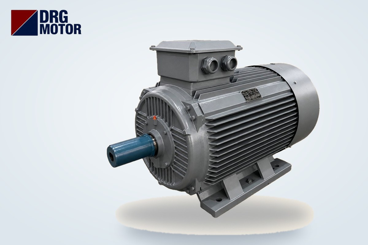

For a 37 kW three-phase motor, the smallest copper cable size based on current-carrying capacity is 4×25 mm² + PE, and for 45 kW it is 4×35 mm² + PE: the 1500 rpm DRG-225S-4 draws 69.6 A at 380 V and the DRG-225M-4 draws 84.4 A; multiplied by 1.25 these currents give design currents of 87.0 A and 105.5 A, which are covered by the 25 mm² cable rated 101 A and the 35 mm² cable rated 126 A in the table. This is an example value for copper, PVC-insulated cable at about 30°C; it must be verified by an electrical engineer according to the installation method, grouping and ambient temperature.
The cable size is not settled by current alone. As the motor moves further from the panel, voltage drop, the 510–630 A starting current, coordination with the protective device and laying the cable together with other cables in a trunking can push the size up by one or two steps. Below we work through these four steps in order, using the catalogue values of the 37 and 45 kW models. You can reach the technical pages and current details of these motors in the Buy Electric Motors Online section.
What Cable Size Does a 37 or 45 kW Motor Need? Quick Answer Table
The table starts from the rated current of six models and shows the design current (In × 1.25) and the smallest cross-section that carries it. Current ratings and resistance values come from the table of our cable size calculator.
| Model | Power / speed | In 380 V | In 400 V | cos φ | Design current | Smallest size (current capacity) |
|---|---|---|---|---|---|---|
| DRG-200L2-2 | 37 kW / 2960 rpm | 67.4 A | 64.0 A | 0.89 | 84.25 A | 25 mm² (101 A) |
| DRG-225S-4 | 37 kW / 1485 rpm | 69.6 A | 66.1 A | 0.86 | 87.0 A | 25 mm² (101 A) |
| DRG-250M-6 | 37 kW / 985 rpm | 71.7 A | 68.1 A | 0.84 | 89.6 A | 25 mm² (101 A) |
| DRG-225M-2 | 45 kW / 2965 rpm | 80.8 A | 76.8 A | 0.90 | 101.0 A | 25 mm² at the limit, 35 mm² recommended |
| DRG-225M-4 | 45 kW / 1485 rpm | 84.4 A | 80.2 A | 0.86 | 105.5 A | 35 mm² (126 A) |
| DRG-280S-6 | 45 kW / 985 rpm | 85.8 A | 81.6 A | 0.85 | 107.25 A | 35 mm² (126 A) |
The design current of the DRG-225M-2 (101.0 A) is exactly equal to the table value of 25 mm². With no margin left for derating, the slightest reduction—inside a trunking, in a warm panel room or on a tray shared with other cables—makes this size insufficient; starting with 35 mm² for 45 kW at every pole number is more consistent.
Step 1: How Is the Cable Size Found from Current-Carrying Capacity?
The first step uses the rated current (In) on the nameplate; there is no need to recalculate the current from the power. The catalogue current already includes the motor's real cos φ and losses. The calculation goes in this order:
- Pick the current matching the supply voltage: the DRG-225S-4 draws 69.6 A at 380 V and 66.1 A at 400 V. Since the voltage measured on site in Türkiye is often between 380 and 400 V, using the higher 380 V current is the safe side.
- Find the design current: Ib = In × 1.25. For 37 kW 4-pole: 69.6 × 1.25 = 87.0 A; for 45 kW 4-pole: 84.4 × 1.25 = 105.5 A.
- From the table, pick the first size whose current rating is equal to or greater than Ib: 25 mm² (101 A) for 87.0 A, 35 mm² (126 A) for 105.5 A.
The 1.25 factor covers short loads above the rated current and calculation uncertainty; it is not meant to cover the starting current. Starting current lasts a few seconds and does not govern cable heating; its effect is handled on the protection side in step 3. To try other ratings quickly, use the motor cable size calculator.
Step 2: When Does the Size Increase as the Cable Gets Longer?
Even when the current rating is sufficient, the voltage reaching the motor terminals drops on a long line; at low voltage the motor draws more current to turn the same shaft and heats up. The formula:
ΔU = √3 × I × (L/1000) × R × cos φ and %ΔU = ΔU / U × 100 (R: Ω/km, L: metres, U: 380 V)
The accepted limit is 3% on the supply line and 5% in total up to the load. Percentage voltage drop for the 37 and 45 kW 4-pole models:
| Cable length | 37 kW – 25 mm² | 37 kW – 35 mm² | 45 kW – 35 mm² | 45 kW – 50 mm² |
|---|---|---|---|---|
| 40 m | 0.79% | 0.57% | 0.69% | 0.51% |
| 80 m | 1.59% | 1.14% | 1.39% | 1.02% |
| 120 m | 2.38% | 1.72% | 2.08% | 1.54% |
| 160 m | 3.17% | 2.29% | 2.77% | 2.05% |
| 200 m | 3.97% | 2.86% | 3.47% | 2.56% |
| Longest run for 3% | 151 m | 210 m | 173 m | 234 m |
The calculations use 69.6 A and cos φ 0.86 for the DRG-225S-4, and 84.4 A and cos φ 0.86 for the DRG-225M-4; resistances are 0.727 Ω/km for 25 mm², 0.524 for 35 mm² and 0.387 for 50 mm².
Example: a 45 kW pump motor 130 m away
A DRG-225M-4 drives a pump 130 m from the panel. With 35 mm², ΔU = 1.732 × 84.4 × 0.13 × 0.524 × 0.86 ≈ 8.56 V, i.e. 2.25%, below the 3% limit. The same motor at 200 m rises to 3.47%; at that distance 50 mm² (2.56%) should be chosen. At 37 kW, 25 mm² is adequate up to 151 m; beyond that, move to 35 mm².
Step 3: How Do Starting Current and Short-Circuit Protection Affect the Size?
With direct-on-line starting, the starting current is found from the Is/In ratio: 69.6 × 7.4 ≈ 515 A for the DRG-225S-4 and 84.4 × 7.4 ≈ 624.6 A for the DRG-225M-4. The cable carries this current for a few seconds, and it affects two things:
- Voltage dip at start: Since voltage drop is proportional to current, the percentages rise roughly 7.4 times at start. On a long, thin line the motor loses starting torque and, with a heavy load, the start takes longer. That is why a larger size, or star-delta or soft starting, is considered together on long runs.
- Choice of protective device: The fuse or motor protection circuit breaker must not trip on starting current, yet it must protect the cable. As the device rating is raised to suit the motor start, check whether the cable withstands the heat during the tripping time of a short circuit (the cable's short-time current withstand). If necessary, the size is increased or the type of protection is changed.
We do not give an exact fuse value here; the manufacturer's tripping curve and the short-circuit current of the installation are decisive. The logic and an example selection are shown in the overload relay, fuse and contactor selection tool.
Step 4: Correcting for Installation Method, Grouping and Ambient Temperature
The 101 A and 126 A values in the table are example ratings for a single cable in free air. On site, these conditions reduce the current a cable can carry:
- Laying the cable in conduit or closed trunking where it cannot shed heat,
- Several loaded cables running side by side on the same tray or trunking (grouping),
- Locations above 30°C such as boiler rooms, roof spaces or sun-exposed façades,
- For buried cables, the thermal properties of the soil and the depth.
For each condition, correction factors from regulations and cable manufacturer tables are used; their product reduces the table current, which is compared with Ib again. For example, if the 126 A rating of 35 mm² drops below 105.5 A after correction on the 45 kW 4-pole motor, the size goes up to 50 mm². Do not guess the factors; get engineering approval for the project.
How Is the 2×(3-Core) Cable Size Calculated for Star-Delta Starting?
All 37 and 45 kW models are rated 400/690 V (Δ/Y); on a 380–400 V supply they run in delta, so they are suitable for star-delta starting. In this arrangement, two separate 3-core cables run from the panel to the motor instead of one: one connects to U1-V1-W1, the other to W2-U2-V2. Each cable carries the winding (phase) current, which is the line current divided by √3.
| Calculation step | 37 kW (DRG-225S-4) | 45 kW (DRG-225M-4) |
|---|---|---|
| Line current In (380 V) | 69.6 A | 84.4 A |
| Winding current In/√3 | 40.18 A | 48.73 A |
| Design current × 1.25 | 50.23 A | 60.91 A |
| Smallest size per cable | 2 × (3×10 mm²) (60 A) | 2 × (3×16 mm²) (80 A) |
| Supply cable to the panel | 4×25 mm² + PE | 4×35 mm² + PE |
At 45 kW the design current is 60.91 A, slightly above the 60 A rating of 10 mm², so the size goes up to 16 mm². With two cable sets, voltage drop is calculated over the two conductors feeding each winding: ΔU ≈ 2 × Iwinding × (L/1000) × R × cos φ. For instance, if the 45 kW motor is 130 m away, 16 mm² gives 2 × 48.73 × 0.13 × 1.15 × 0.86 ≈ 12.5 V, i.e. 3.30%, exceeding the limit; with 2 × (3×25 mm²) it drops to 2.08%. Two thin cable sets suffice on a short run, but this advantage shrinks on a long one. The PE conductor is run separately or included in one of the cables. For contactor and overload currents in star-delta, see the star-delta starting tool; for the starting current and torque of these ratings, see our article how many amps a 37 and 45 kW motor draws.
Terminal Box, Cable Entry and Checklist Before Pulling the Cable
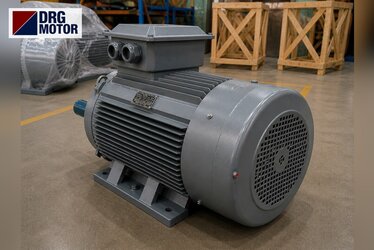
Once the size is set, check that the cable can physically enter the motor. According to catalogue data, the cable entry is 2 × M50×1.5 on 37/45 kW models with 200L, 225S and 225M frames, and 2 × M63×1.5 on 250M and 280S frames. Two entries allow the two star-delta cable sets to enter through separate glands. When choosing a gland, make sure the cable's outer diameter falls within its clamping range; since the outer diameter depends on cable construction, check it in the cable datasheet. For terminal box protection and entry details, the article on the motor terminal box and cable entry is useful.
- I read the nameplate In for 380 V and 400 V and used the 380 V current in the calculation.
- I calculated the design current (In × 1.25) and picked the first adequate size from the table.
- I calculated voltage drop with the real cable length; if it exceeded 3%, I moved up one size.
- I had the correction for installation method, grouping and ambient temperature verified by an engineer.
- I checked that the protective device does not trip on starting current and protects the cable under short circuit.
- For star-delta, I made sure both cable sets have the same size and the same length.
- I confirmed that the cable outer diameter matches the gland (M50 or M63) clamping range and that the lugs suit the terminal studs.
- I connected the PE conductor to the earthing screw on the motor frame and in the terminal box.
37 and 45 kW Motor Models
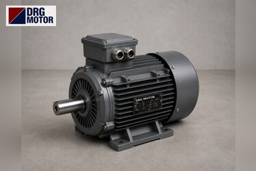
Cast iron frame models used in the calculations in this article:
- DRG-200L2-2 – 37 kW – 3000 rpm – 200L cast iron
- DRG-225S-4 – 37 kW – 1500 rpm – 225S cast iron
- DRG-250M-6 – 37 kW – 1000 rpm – 250M cast iron
- DRG-225M-2 – 45 kW – 3000 rpm – 225M cast iron
- DRG-225M-4 – 45 kW – 1500 rpm – 225M cast iron
- DRG-280S-6 – 45 kW – 1000 rpm – 280S cast iron
Click to see current prices and order these motors nowSEE PRICES →
Frequently Asked Questions
What size cable for a 37 kW motor?
For the 1500 rpm DRG-225S-4 the design current is 87.0 A; for copper, PVC cable at about 30°C, 4×25 mm² + PE is sufficient for current capacity. If the run exceeds 151 m, voltage drop goes above 3%, so 35 mm² is chosen. Trunking and grouping correction may increase the size.
Is 25 mm² cable enough for a 45 kW motor?
It is not recommended. The design current of the 1500 rpm DRG-225M-4 is 105.5 A, above the 101 A rating of 25 mm². Even for the 3000 rpm DRG-225M-2 the design current of 101.0 A is right at the limit; the starting size for 45 kW is 35 mm².
What cable size for a 45 kW star-delta motor?
The winding current is 84.4 / √3 ≈ 48.73 A and the design current 60.91 A; on a short run 2 × (3×16 mm²) is enough on the motor side. The supply line to the panel carries the full line current, so it is sized as 4×35 mm² + PE. On a long run, voltage drop of the two sets is checked separately.
At what cable length should the size be increased for a 37 kW motor?
For the DRG-225S-4 (69.6 A, cos φ 0.86), 3% voltage drop is reached at about 151 m with 25 mm² cable and about 210 m with 35 mm². Beyond these distances, move up one size.
To choose the right 37 or 45 kW motor for your project and discuss cable and connection details, call us on +90 (542) 666 11 11, write to [email protected] or use our contact page. All power and speed options are among the 120 models in our online store.