English
 Le français
 Türkçe




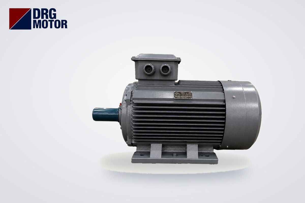

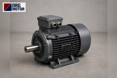
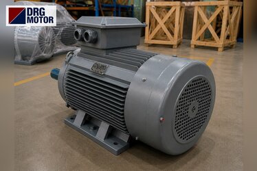
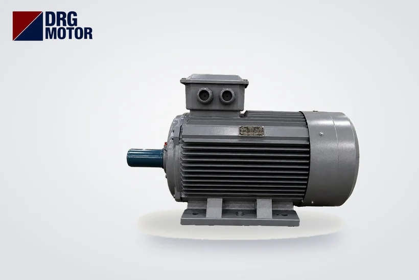
A three-phase asynchronous motor is an electric motor in which the rotating magnetic field created by a stator fed from a three-phase supply induces current in the rotor conductors and turns the rotor. The rotor never quite catches up with this field; it runs slightly below synchronous speed, and the difference is called slip. For example, on a 50 Hz supply a 4-pole motor has a synchronous speed of 1500 rpm, while the DRG-112M-4 (4 kW) runs at 1450 rpm at full load; the slip is about 3.3%. Its construction is simple (stator, squirrel-cage rotor, two bearings, fan and terminal box) and it has no brushes or commutator, which makes it the standard industrial drive for pumps, fans, compressors and conveyors.
The word “asynchronous” comes from this lack of synchronism in speed, and “three-phase” from the way it is supplied; in the field the same motor is also called an induction motor. Rather than repeating the general definition, this article covers the three-phase motor with catalogue data: slip calculated from real values, frame and bearing differences by power, reading the nameplate and selection steps. For 120 models that can be filtered by power, speed and frame, see our Buy Electric Motors Online page. For the general principle and rotor types, our existing article What Is an Asynchronous Motor, and for single-phase versions What Is a Single-Phase Induction Motor?, are also worth reading.
How Does a Three-Phase Asynchronous Motor Work?
The stator contains three winding groups placed 120° apart from each other. When three phase voltages that are also shifted by 120° in time are applied to these windings, the field of each winding pulsates on its own, but their sum forms a single magnetic field that rotates with constant amplitude and constant speed. This is the key feature that separates the three-phase motor from the single-phase motor: the rotating field forms by itself, and no auxiliary winding or capacitor is needed for starting.
The rotating field cuts the rotor bars and induces a voltage in them. Because the rotor bars are joined at both ends by short-circuit rings, this voltage drives a large rotor current; a current-carrying conductor in a magnetic field experiences a force, and the rotor starts to turn in the direction of the field. If the rotor reached synchronous speed, the field would no longer cut the bars, and current and torque would fall to zero. That is why an asynchronous motor produces torque only when there is slip; as load increases, slip increases, the motor slows slightly and draws more current.
The direction of the rotating field is set by the phase sequence. Swapping any two phases in the supply cable reverses the field and the motor; details are in our article Why Does an Electric Motor Run Backwards?
How Are Synchronous Speed and Slip Calculated?
Synchronous speed depends on supply frequency and the number of poles: ns = 120 · f / p (f: Hz, p: number of poles). At 50 Hz this gives 3000 rpm for 2 poles, 1500 for 4 poles, 1000 for 6 poles and 750 rpm for 8 poles. Slip is calculated as s = (ns − n) / ns, where n is the rated speed on the nameplate. The frequency of the rotor current is f₂ = s · f and at full load is only a few hertz.
| Model | Power | Poles | Synchronous speed | Rated speed | Slip | Rotor frequency |
|---|---|---|---|---|---|---|
| DRG-160M1-2 | 11 kW | 2 | 3000 rpm | 2945 rpm | ≈ 1.8% | ≈ 0.92 Hz |
| DRG-160M-4 | 11 kW | 4 | 1500 rpm | 1465 rpm | ≈ 2.3% | ≈ 1.17 Hz |
| DRG-160L-6 | 11 kW | 6 | 1000 rpm | 970 rpm | 3.0% | 1.5 Hz |
| DRG-711-4 | 0.25 kW | 4 | 1500 rpm | 1340 rpm | ≈ 10.7% | ≈ 5.33 Hz |
| DRG-355M-4 | 250 kW | 4 | 1500 rpm | 1490 rpm | ≈ 0.67% | ≈ 0.33 Hz |
Two conclusions follow from the table. First, at the same power (11 kW), slip grows as the number of poles increases. Second, slip becomes clearly smaller as power grows: the 0.25 kW motor runs 160 rpm below synchronous speed, while the 250 kW motor runs only 10 rpm below. Worked example: for the DRG-160L-6, s = (1000 − 970) / 1000 = 0.03, i.e. 3%; rotor frequency is 0.03 × 50 = 1.5 Hz. The three-phase models in our store are 2-, 4- and 6-pole; 8-pole (750 rpm) motors are not part of this range.
Construction and Parts of a Three-Phase Asynchronous Motor
- Stator: The three-phase winding is placed in slots inside a core stacked from thin, insulated electrical steel laminations. The winding ends are brought out to the terminal box as six terminals (U1, V1, W1, U2, V2, W2), so the motor can be connected in star or delta.
- Rotor: In standard motors it is a squirrel-cage type; aluminium bars are cast into the slots of the lamination stack and joined at the ends by short-circuit rings. There is no external connection to the rotor.
- Shaft and bearings: The rotor is carried by two bearings in the front and rear end shields. Bearing size increases with frame size (table below).
- Fan and fan cover: A shaft-mounted fan blows air over the finned frame to cool the motor; the fan cover also acts as a guard.
- Terminal box: The supply cable enters through a cable gland, the connection is selected with links, and the earthing screw is located here.
- Frame and feet/flange: The frame can be aluminium or cast iron; foot (B3) or flange (B5) mounting determines how it is installed.
| Model | Power / speed | IEC frame | Frame material | Bearing | Shaft diameter D | Cable entry |
|---|---|---|---|---|---|---|
| DRG-711-4 | 0.25 kW / 1340 rpm | 71 | Aluminium | 6202-ZZ-C3 | 14 mm | 1 × M20×1.5 |
| DRG-90L-4 | 1.5 kW / 1445 rpm | 90L | Aluminium | 6205-ZZ-C3 | 24 mm | 1 × M25×1.5 |
| DRG-112M-4 | 4 kW / 1450 rpm | 112M | Cast iron | 6206-ZZ-C3 | 28 mm | 2 × M32×1.5 |
| DRG-160L-4 | 15 kW / 1465 rpm | 160L | Cast iron | 6309-C3 | 42 mm | 2 × M40×1.5 |
| DRG-280S-4 | 75 kW / 1486 rpm | 280S | Cast iron | 6317-C3 | 75 mm | 2 × M63×1.5 |
| DRG-355M-4 | 250 kW / 1490 rpm | 355M | Cast iron | 6322-C3 | 100 mm | 2 × M63×1.5 |
In small frames, “ZZ” in the bearing code means a bearing with metal shields on both sides, and “C3” on all models means an internal clearance larger than standard. The frame number (71, 112, 160…) is also the height of the shaft centre above the foot base (mm); for foot hole dimensions, see our article B3 Foot-Mounted Motor Dimensions.
Types of Three-Phase Asynchronous Motors
By rotor type: squirrel cage and slip ring
The squirrel-cage motor has no rubbing parts that need maintenance and is used in almost all general-purpose applications. In the slip-ring (wound-rotor) motor, the rotor winding is connected to external resistors through slip rings and brushes; it is found in older installations with very heavy starting, and today most of that need is met by a squirrel-cage motor with a frequency converter. All DRG products have squirrel-cage rotors.
By frame material: aluminium and cast iron
Of the 120 models in our store, 38 have aluminium frames (0.25–11 kW) and 82 have cast iron frames (0.55–355 kW); three models are a compact series. The aluminium frame is light and helps at small powers for handling, flange mounting and use inside machines. The cast iron frame is more rigid; it is preferred in vibrating, dusty or impact-prone environments and at high powers.
By mounting: B3, B5, B35, B14
B3 means horizontal foot mounting, B5 large flange mounting, B35 combined foot and flange mounting, and B14 a small (tapped-hole) flange. B5 or B14 is used on machines bolted directly by flange, such as pumps and gearboxes, and B3 for coupled drives on a base frame.
How to Read a Motor Nameplate
The nameplate carries all the information needed to connect and protect the motor correctly. As an example, the DRG-112M-4 catalogue values:
- Power: 4 kW (5.5 HP). This is the mechanical power available at the shaft; the power drawn from the supply is higher.
- Voltage: 400/690 V (Δ/Y). On a 380–400 V supply it is connected in delta. On our models below 4 kW the nameplate reads 230/400 V (Δ/Y) and the motor is connected in star on 380 V. This difference also determines whether star-delta starting is possible.
- Current: 8.37 A at 380 V, 7.95 A at 400 V. As voltage rises, the current for the same power falls; in a 690 V star connection the current is about 7.95 × 400 / 690 ≈ 4.6 A.
- Rated speed: 1450 rpm; slip is calculated from this.
- cos φ: 0.82. It shows the share of reactive power drawn from the supply and is used in power factor correction calculations.
- Catalogue torque values: Rated torque 26.3 Nm (T = 9550 · P / n = 9550 × 4 / 1450 ≈ 26.3 Nm), starting torque ratio Ts/Tn = 2.2, breakdown torque ratio Tmax/Tn = 2.3, starting current ratio Is/In = 7.8. Accordingly, about 8.37 × 7.8 ≈ 65.3 A and 2.2 × 26.3 ≈ 57.9 Nm are expected at start.
You can check the cable size for the nameplate current with our Motor Cable Size Calculator and the currents of other powers with the Motor Current Chart.
Where Are Three-Phase Asynchronous Motors Used?
They are used in every facility with a three-phase supply, on almost any machine that needs rotary motion at fixed speed or at a speed adjusted with a frequency converter. Speed selection depends on the application:
- 3000 rpm (2-pole): Centrifugal pumps, booster sets and high-speed fans, grinders and some compressors.
- 1500 rpm (4-pole): Conveyors and belts, geared drives, screw compressors, mixers, general machine building. This is the most common speed in the field.
- 1000 rpm (6-pole): Crushers, mills, large-diameter fans and loads needing more torque at the same power. The rated torque of the DRG-160L-6 is 108.3 Nm, while that of the DRG-160M1-2 at the same 11 kW is 35.7 Nm.
Agricultural irrigation pumps, concrete batching plants, stone crushing plants, ventilation systems, and food and textile machinery are typical applications for these motors. If the application needs variable speed, the motor is driven by a frequency converter; in that case cooling at low speed is assessed separately.
Checklist for Choosing a Three-Phase Motor
- Power: Determine the shaft power the machine needs; when replacing an old motor, use its nameplate power.
- Speed: Choose 2, 4 or 6 poles according to machine speed; take belt or gearbox ratio into account.
- Supply and connection: On a 380–400 V supply a 230/400 V motor is connected in star and a 400/690 V motor in delta; if star-delta starting is required, choose a 400/690 V model.
- Starting duty: For heavy-starting loads, check the Ts/Tn and Is/In values in the catalogue.
- Frame and mounting: IEC frame number, shaft diameter and B3/B5/B35/B14 mounting must match the existing machine.
- Frame material and environment: Aluminium where low weight matters, cast iron in harsh environments and at high power.
- Protection and cable: Select overload relay, fuse and cable size from the nameplate current; our Electric Motor Calculators page covers these calculations.
Examples of Three-Phase Asynchronous Motors in Our Online Store
The models below are taken from different power and frame groups; all options are listed by power, speed and frame on the store page.
- DRG-90L-4 – 1.5 kW – 1500 rpm – 90L aluminium
- DRG-112M-4 – 4 kW – 1500 rpm – 112M cast iron
- DRG-112M-4K – 5.5 kW – 1500 rpm – 112M aluminium (compact)
- DRG-160M-4 – 11 kW – 1500 rpm – 160M aluminium
- DRG-160L-4 – 15 kW – 1500 rpm – 160L cast iron
- DRG-280S-4 – 75 kW – 1500 rpm – 280S cast iron
Click to see current prices and order these motors nowSEE PRICES →
Frequently Asked Questions
Is a three-phase asynchronous motor the same as a three-phase induction motor?
Yes. In the field, three-phase motor, three-phase induction motor and three-phase asynchronous motor all refer to the same squirrel-cage motor. A synchronous motor is a different type whose rotor turns at the same speed as the rotating field.
What should the slip of a three-phase asynchronous motor be?
Slip depends on power and number of poles; there is no single correct value. In our catalogue data it is about 10.7% for a 0.25 kW 4-pole motor, about 2.3% for an 11 kW 4-pole motor and about 0.67% for a 250 kW 4-pole motor. For your own motor, simply enter the nameplate speed into s = (ns − n) / ns.
Will a three-phase motor run on 220 V?
A three-phase motor is designed for a three-phase supply. Small motors rated 230/400 V run on a 230 V three-phase network when connected in delta; on a single-phase 220 V socket they can only be run with extra solutions such as a capacitor or a single-phase-input frequency converter, and with a loss of power. If only a single-phase supply is available, a single-phase motor may be more suitable.
How is the speed of a three-phase asynchronous motor adjusted?
Because speed depends on synchronous speed, it is adjusted by changing the frequency in ns = 120 · f / p; a frequency converter does this. The number of poles is fixed by the motor design; machine speed can also be changed with belts and pulleys or a gearbox.
Contact us to choose the right three-phase motor for your application together: +90 (542) 666 11 11 · [email protected] · Contact. All power, speed and frame options are among the 120 models in our online store.