English
 Le français
 Türkçe




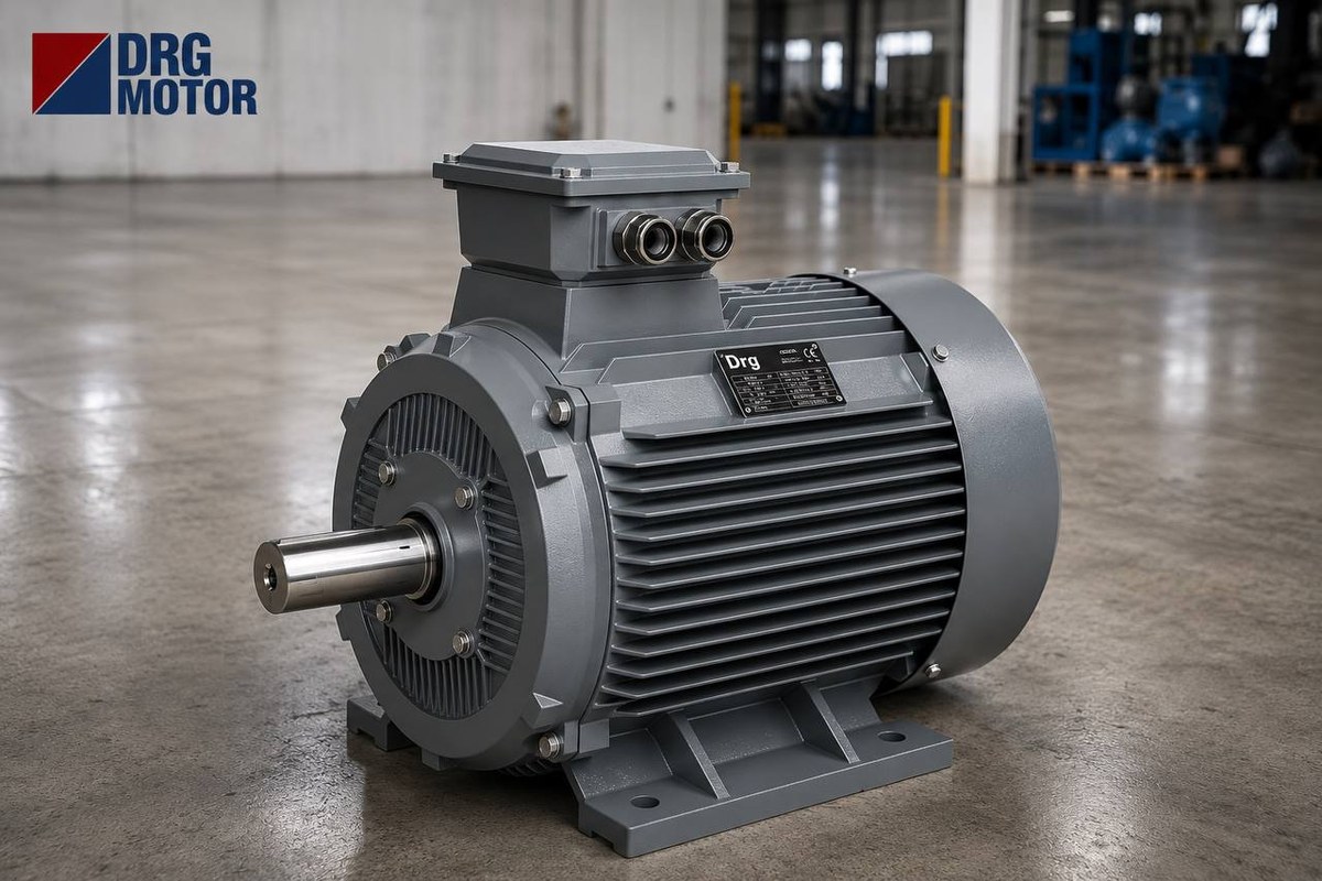

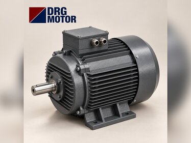
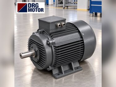
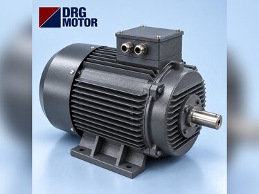
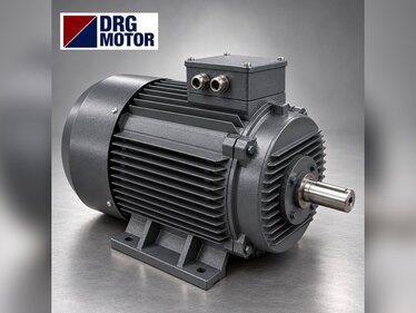
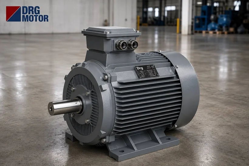
On workshop and mid-size universal lathes, the main motor that drives the spindle is usually a 4-pole three-phase induction motor, i.e. about 1500 rpm synchronous speed; most machines fall in the 2.2–7.5 kW range, but the exact value is on the lathe's rating plate or in its maker's data. As an example, the 5.5 kW DRG-132S-4 delivers 36.0 Nm at its rated speed of 1460 rpm and draws 10.7 A at 400 V; the belt and gearbox multiply this torque before it reaches the spindle.
The power you need depends less on the size of the lathe than on the chip cross-section you remove: on the same machine a finishing pass stays below 1 kW, while a deep roughing pass in steel pushes the motor to its plate rating. For a maintenance technician replacing a failed motor the rule is simple: read power, speed, shaft size and mounting from the plate and choose the same. Wiring and protection settings must be done by a qualified electrician. You can find the right frame among the 120 models on our Buy Electric Motors Online page using the power and speed filters.
Spindle Drive: Belt, Gearbox and Why 4 Poles?
On a conventional lathe the motor sits in the lower part of the bed on an adjustable motor plate or slide rail. The motor pulley drives the gearbox input shaft through V-belts, and the gearbox levers select the spindle speed in steps. The motor therefore always runs close to its rated speed, and the mechanical transmission handles the speed change.
There are three reasons for choosing 4 poles. First, torque: at the same power a 4-pole motor produces roughly twice the torque of a 2-pole one, so the gear ratio stays reasonable in the low gearbox steps. Second, noise and vibration: a pulley and belt running around 1500 rpm give a calmer drive for precision surface work. Third, compatibility: the machine design, pulley diameters and gear ratios were calculated for this speed; fitting a 3000 rpm motor in place of the old one doubles the whole speed chart.
The direction of rotation changes often for threading and retracting; this is done in the panel with two contactors swapping phases or with a frequency inverter, and the motor itself needs no special feature.
Cutting Power Calculation: Pc = Fc · vc / 60000
The most practical way to estimate motor power for a lathe is to start from the cutting force. The cutting force is Fc = kc · ap · f, where kc is the specific cutting force (N/mm²), ap the depth of cut (mm) and f the feed (mm/rev). The cutting power is then Pc = Fc · vc / 60000 (kW), with vc the cutting speed (m/min).
The assumptions in the table below are stated openly: kc = 2000 N/mm² as a rounded value for medium carbon steel, vc = 120 m/min, and motor power = Pc × 1.25 to cover belt, gear and bearing losses plus a starting margin. The real kc varies with material, tool geometry and chip thickness; the table shows an order of magnitude and does not replace a measurement.
| Pass type | ap (mm) | f (mm/rev) | Fc (N) | Pc (kW) | Pc × 1.25 (kW) |
|---|---|---|---|---|---|
| Finishing | 1 | 0.2 | 400 | 0.8 | 1.0 |
| Medium | 2 | 0.3 | 1200 | 2.4 | 3.0 |
| Roughing | 3 | 0.3 | 1800 | 3.6 | 4.5 |
| Heavy roughing | 4 | 0.4 | 3200 | 6.4 | 8.0 |
With these assumptions, a 3 mm depth and 0.3 mm/rev feed give a cutting power of 3.6 kW and a motor power with margin of about 4.5 kW; the nearest standard size above is 5.5 kW. If your lathe only does finishing and medium passes, 3 kW may be enough; on a machine that often takes heavy cuts, keep the same power rather than downsizing the existing motor. The plate power was chosen with the bed, spindle bearings and gears in mind; oversizing the motor far beyond the plate strains the mechanics.
Torque at the Spindle: How Does a Small Motor Turn a Large Diameter?
Power alone is not enough; on large-diameter work the real limit is torque. Turning a Ø80 mm shaft at 120 m/min requires a spindle speed of n = vc · 1000 / (π · D) ≈ 477 rpm. At this speed, 3.6 kW of cutting power needs a torque of about 72 Nm according to T = 9550 · P / n.
The rated torque of the DRG-132S-4 is 36.0 Nm, which looks insufficient at first sight. But if the motor turns at 1460 rpm while the spindle turns at 477 rpm, the ratio is 1460 / 477 ≈ 3.06, giving (losses excluded) 36.0 × 3.06 ≈ 110 Nm at the spindle. The low gearbox steps do exactly this: they lower the speed and raise the torque by the same ratio.
The starting moment matters too. A heavy chuck with a clamped workpiece means large inertia; on the DRG-132S-4 the starting torque ratio is Ts/Tn = 2.0 and the starting current ratio Is/In = 7.9. On a lathe with frequent start-stop, the overload relay and fuse must be selected for this starting current; you can compare values by power on the motor current chart page.
Stepless Speed with a Frequency Inverter: Is the Gearbox Still Needed?
Replacing the gear levers on an old lathe with stepless speed control through a frequency inverter is a common upgrade. Raising the speed as the diameter drops, at constant cutting speed, improves surface finish. Even so, taking the gearbox out of service entirely is usually a mistake.
Example: facing a Ø300 mm flange at the same 120 m/min requires about 127 rpm at the spindle. If the ratio stays fixed at 3.06, the motor must drop to 389 rpm, i.e. about 13.3 Hz. In the constant-torque region the power a motor can deliver falls in proportion to speed, so the 5.5 kW motor can only give about 1.5 kW at this point; power is lost exactly where the highest torque is needed. For this reason at least two mechanical steps (low and high) should be kept even with an inverter.
At low frequency the motor's own fan slows down as well; watch winding temperature on a motor that will run under load at low frequency for long periods. For the insulation and forced cooling decision see insulation and forced cooling for VFD-driven motors, and to see torque and power versus frequency use the VFD frequency-torque-power calculator.
Replacing the Motor on an Old Lathe: Shaft, Pulley and Foot Fit
When changing the motor on a decades-old lathe, the most frequent problem is not power but dimensions. The old motor may predate the IEC standard; if the shaft diameter, shaft height or foot hole spacing differs from the new motor, an adapter plate or a new pulley is needed. Foot-mounted B3 is standard on DRG motors; on lathes where the motor bolts to the gearbox with a flange, B35 (feet plus flange) is chosen. Stating the mounting option in the order is enough.
Before ordering, measure and note the following on the old motor:
- Plate power (kW), rated speed and voltage connection; if unreadable, estimate the frame from shaft diameter and frame height.
- Shaft diameter and length (D × E) and key width (F): 28 × 60 mm and 8 mm on 100L and 112M frames, 38 × 80 mm and 10 mm on 132S and 132M frames.
- Shaft centre height (H) and foot hole spacing (A × B): on the 112M frame H = 112 mm, A × B = 190 × 140 mm.
- Pulley bore and keyway: if the old pulley does not fit the new shaft, have the pulley re-machined to the motor shaft; never turn the shaft down to suit the pulley.
- Pulley diameter: the motor speed must stay the same, otherwise the spindle speed steps shift. Check any ratio change with the pulley and belt calculator.
- Connection: models of 3 kW and below are 230/400 V and are star-connected on a 400 V supply; 4 kW and above are 400/690 V and run in delta on a 400 V supply.
- Belt alignment and tension: after bolting the new motor to the plate, align the pulleys with a straight edge.
Which DRG Motor Should I Buy? 4-Pole Models for Lathes
Because it damps vibration in the machine bed and offers a rigid foot connection, a cast iron frame is a suitable choice for a lathe. The values in the table are catalogue data; match the row to the power and speed on the plate.
| Model | Power (kW) | Rated speed (rpm) | Frame | Current 400 V (A) | Torque (Nm) | Shaft D × E (mm) |
|---|---|---|---|---|---|---|
| DRG-90L-4 | 1.5 | 1445 | 90L | 3.3 | 9.91 | 24 × 50 |
| DRG-100L1-4 | 2.2 | 1450 | 100L | 4.52 | 14.5 | 28 × 60 |
| DRG-100L2-4 | 3 | 1450 | 100L | 6.02 | 19.8 | 28 × 60 |
| DRG-112M-4 | 4 | 1450 | 112M | 7.95 | 26.3 | 28 × 60 |
| DRG-132S-4 | 5.5 | 1460 | 132S | 10.7 | 36.0 | 38 × 80 |
| DRG-132M-4 | 7.5 | 1460 | 132M | 14.3 | 49.1 | 38 × 80 |
Note where two powers share one frame: the DRG-100L1-4 and DRG-100L2-4 share the same 100L frame and 28 × 60 mm shaft. On a lathe that keeps tripping a 2.2 kW motor, if there is a genuine need for heavy cuts and the mechanics allow it, moving to 3 kW with the same mounting dimensions is possible. The 5.5 kW and 7.5 kW models also share the 38 × 80 mm shaft on the 132 frame, but the foot spacing B differs (140 and 178 mm).
Motors in This Power Range
- DRG-100L1-4 – 2.2 kW – 1450 rpm – 100L
- DRG-100L2-4 – 3 kW – 1450 rpm – 100L
- DRG-112M-4 – 4 kW – 1450 rpm – 112M
- DRG-132S-4 – 5.5 kW – 1460 rpm – 132S
- DRG-132M-4 – 7.5 kW – 1460 rpm – 132M
Click to see current prices and order these motors nowSEE PRICES →
Frequently Asked Questions
What speed should a lathe motor be?
On conventional lathes with belt and gearbox the motor is mostly 4-pole, about 1500 rpm synchronous; for the DRG models in the table above the rated speed is 1445–1460 rpm. When replacing, keep the old motor's speed, otherwise every speed step on the machine shifts.
How many amps does a 3 kW lathe motor draw?
The 3 kW, 1500 rpm DRG-100L2-4 draws 6.02 A at 400 V and 6.34 A at 380 V at full load; its power factor is cos φ = 0.82. During a finishing pass the current stays well below this value.
Can a 3000 rpm motor be fitted to a lathe?
It is not recommended on a machine designed for 1500 rpm. The spindle speeds double, torque at the same power halves and the pulley ratio has to be changed. To keep the existing speed chart, choose a motor with the same number of poles.
The old lathe motor's plate is unreadable — which motor should I buy?
Measure the shaft diameter, the shaft centre height (H) and the foot hole spacing. For example, a 28 mm shaft and an H of 112 mm point to a 112M frame; the 4-pole model in this frame is the 4 kW DRG-112M-4. Send us the measurements and we can confirm the frame together.
Share your lathe's plate data and shaft dimensions and we will determine the right motor together: +90 (542) 666 11 11, [email protected] or our contact page. For all models see Buy Electric Motors Online.