English
 Le français
 Türkçe




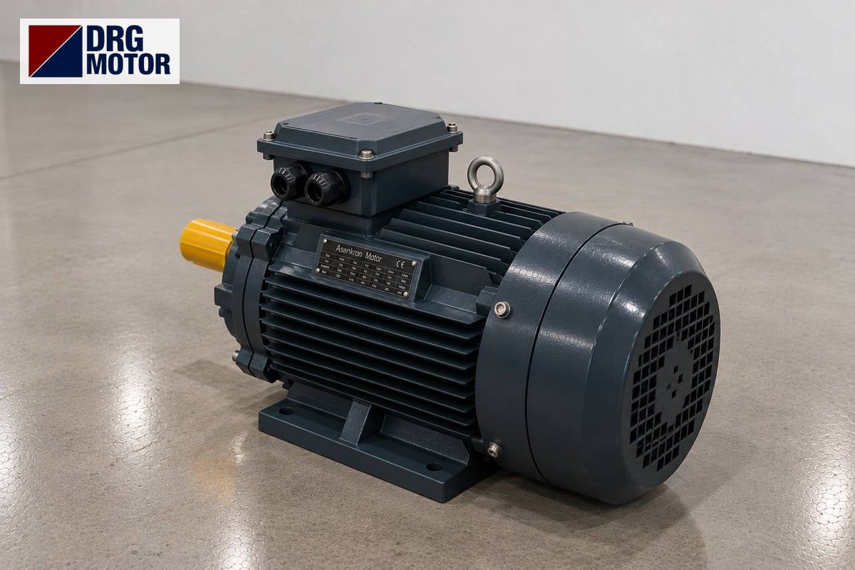

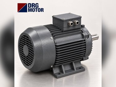
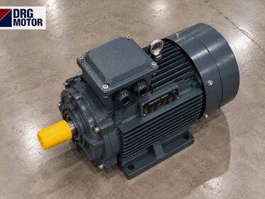
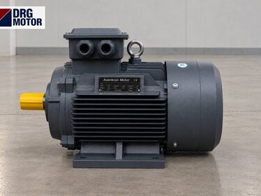
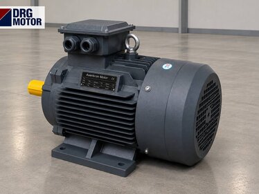
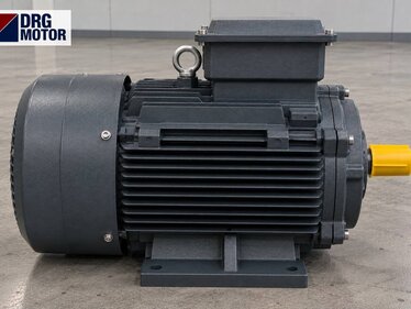
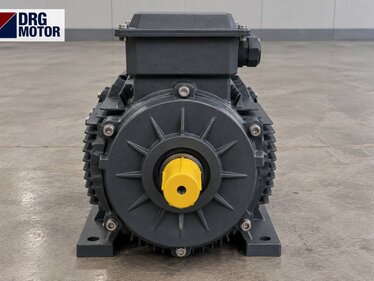
On a shot blasting machine the turbine motor usually carries the blast wheel directly on its own shaft end, so the right motor is a flange-mounted three-phase motor that matches the machine's power, speed and shaft size (D×E) all at once. For example, the 7.5 kW, 3000 rpm class DRG-132S2-2 runs at a rated 2930 rpm, draws 13.7 A at 400 V and has a Ø38×80 mm shaft end; the 4-pole DRG-132M-4 of the same power runs at 1460 rpm, i.e. it turns the same wheel at roughly half the speed. Motor power per turbine is a few kW on small cabinet machines and can reach the 15–22 kW band on large hanger and belt machines; the exact value is given by the machine's nameplate and its builder.
The turbine motor works under the harshest conditions on a blasting machine: as the blades wear the wheel goes out of balance, abrasive dust attacks the shaft seal and flange face, and vibration goes straight into the front bearing. Below you will find how to check speed and power from the abrasive flow, flange and shaft compatibility, protection against dust, and the motor replacement procedure step by step. You can pick a suitable model from the 120 models on our Buy Electric Motors Online page. Removing and fitting the motor is mechanical work, but disconnecting the supply cable, the terminal connection and checking the direction of rotation must be done by a qualified electrician.
What Does the Turbine Motor Carry? Wheel, Shaft and Front Bearing
In a direct-coupled turbine the wheel hub is keyed onto the motor shaft and sits very close to the flange. The motor's front (drive-end) bearing carries both the weight of the wheel and the unbalance force generated during rotation. The further the wheel overhangs from the shaft shoulder, the larger the bending moment on the bearing; so the wheel hub must sit fully against the shaft shoulder and be secured axially with a bolt and washer in the centre hole of the shaft end.
On DRG motors the front bearing depends on the frame: 6208-ZZ-C3 on frame 132, 6309-C3 on frame 160 and 6311-C3 on frame 180. A C3-clearance bearing leaves room for the expansion of the shaft as it warms up in operation. In belt-driven turbines the wheel sits in a separate bearing unit; the motor bearing then carries belt tension rather than the wheel weight. This article focuses on the direct-coupled design, because that is where most mistakes are made during motor replacement.
Inside the turbine the abrasive drops from the feed spout into the distributor (impeller), passes through the window of the control cage onto the blades and is thrown from the blade tips onto the workpiece. From the motor's point of view the key point is this: with the wheel idling the motor draws a low current, and the load comes on the moment the abrasive valve opens. The difference in current between these two states is the most practical measurement showing whether the turbine is really working.
Speed Selection: How to Calculate Wheel Tip Speed
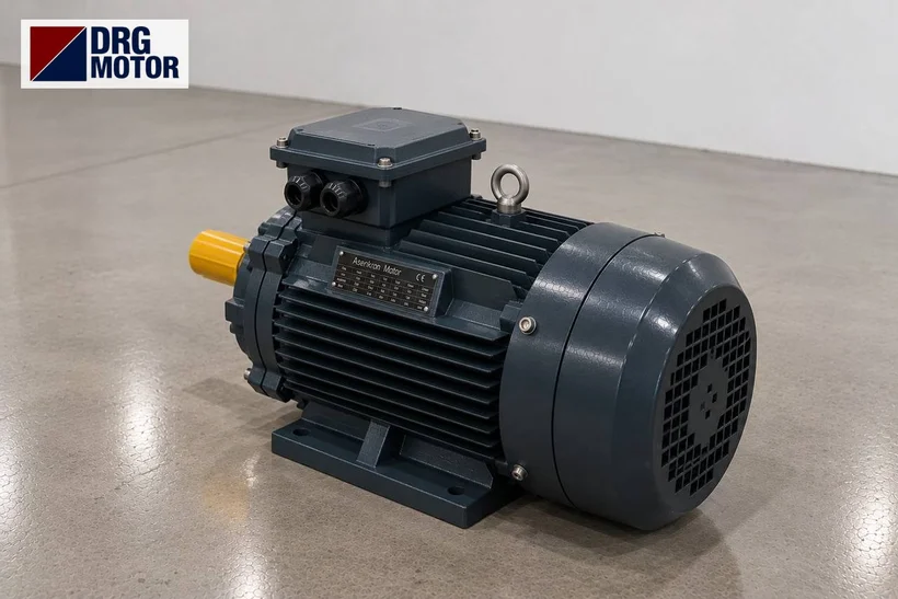
What determines the impact speed of the abrasive on the part is the tip speed of the blades: v = π · D · n / 60 (D: wheel diameter, m; n: speed, rpm; v: m/s). The same wheel produces very different speeds on a 2-pole and a 4-pole motor. The wheel diameters in the table below are chosen as examples; the speeds are the rated values of DRG-132S2-2 (2930 rpm) and DRG-132M-4 (1460 rpm).
| Wheel diameter (assumed) | 2-pole, 2930 rpm | 4-pole, 1460 rpm |
|---|---|---|
| 360 mm | 55.2 m/s | 27.5 m/s |
| 420 mm | 64.4 m/s | 32.1 m/s |
| 500 mm | 76.7 m/s | 38.2 m/s |
The energy transferred to each grain varies with the square of the speed: (1460 / 2930)² ≈ 0.25. So if you fit a 4-pole motor instead of a 2-pole one on the same wheel, each grain strikes with roughly a quarter of the energy; rust and mill scale are not removed and the surface profile is not achieved. The reverse is dangerous too: driving a wheel designed for 4 poles with a 2-pole motor can exceed the permissible speed of the blades and hub. The rule is simple: keep the pole number of the old motor; if a speed change is needed, get the wheel manufacturer's approval.
On machines with a frequency inverter, speed and therefore tip speed can be adjusted with frequency. At low frequency the motor's own fan also slows down and cooling falls; on turbines that will run at low speed for long periods, monitor the motor temperature.
Power Check: A Rough Estimate from the Abrasive Flow
Most of the turbine's power goes into accelerating the abrasive. For a rough check, kinetic power: P = ṁ · v² / 2. Assumptions: abrasive flow 100 kg/min (≈1.67 kg/s), 500 mm wheel, 2930 rpm → v = 76.7 m/s.
- Kinetic power: 1.67 × 76.7² / 2 ≈ 4.9 kW
- Assumed conversion factor for friction, windage and blade losses in the wheel k = 0.7: 4.9 / 0.7 ≈ 7.0 kW
- Next standard power up: 7.5 kW → DRG-132S2-2
- Torque check: T = 9550 · P / n = 9550 × 7.5 / 2930 ≈ 24.4 Nm; the catalogue rated torque is also 24.4 Nm.
The factor k varies from machine to machine; this calculation only helps you see whether the nameplate power is reasonable. The real check is a current measurement: with the machine running at full abrasive feed, the current must not exceed the motor's rated current at 400 V. If the current is above rated, first look at the abrasive valve setting and the wheel diameter; if it stays close to the no-load value, the feed is blocked or the control cage window is in the wrong position.
DRG models by turbine power
| Model | Power / speed | Frame | Current 400 V |
|---|---|---|---|
| DRG-112M-2 | 4 kW / 2905 rpm | 112M cast iron | 7.45 A |
| DRG-132S1-2 | 5.5 kW / 2930 rpm | 132S cast iron | 10.1 A |
| DRG-132S2-2 | 7.5 kW / 2930 rpm | 132S cast iron | 13.7 A |
| DRG-160M1-2 | 11 kW / 2945 rpm | 160M cast iron | 19.6 A |
| DRG-160M2-2 | 15 kW / 2945 rpm | 160M cast iron | 26.5 A |
| DRG-132M-4 | 7.5 kW / 1460 rpm | 132M cast iron | 14.3 A |
Mounting: B5 Flange, B35 and Shaft D×E Compatibility
In most direct-coupled turbines the motor is bolted to the turbine housing with a large flange (B5); if the motor also sits on a bracket, a foot-and-flange B35 design is used. On DRG product pages the mounting options are listed as B3, B5, B14 and B35, and the choice is stated in the order note. The flange of the new motor must be identical to the old one; even a 1 mm difference in the spigot makes the wheel run eccentrically inside the housing.
| Frame | Shaft D×E | Flange P / M / N | Hole S |
|---|---|---|---|
| 112M | 28 × 60 mm | 250 / 215 / 180 mm | 14.5 mm |
| 132S | 38 × 80 mm | 300 / 265 / 230 mm | 14.5 mm |
| 160M | 42 × 110 mm | 350 / 300 / 250 mm | 18.5 mm |
| 180M (2-pole) | 48 × 110 mm | 350 / 300 / 250 mm | 18.5 mm |
P is the flange outside diameter, M the bolt circle diameter and N the spigot (pilot) diameter. Measure these three dimensions, the hole diameter, the shaft diameter and length and the key width (10 mm on 132S, 12 mm on 160M) on the old motor and compare them with the table. If the shaft length (E) is longer than on the old motor, the wheel hub will not seat against the shoulder and the wheel will be left floating on the shaft end; if it is shorter, the hub will not fully engage the shaft. For detailed dimension drawings see the DRG motor technical drawings page.
Protecting the Motor Against Abrasive Dust
DRG motors have IP55 protection. The first digit 5 in IP55 means "dust-protected", not "dust-tight"; so a motor permanently exposed to steel grit and corundum dust escaping from the cabinet still needs precautions. We covered the subject in general in our article on IP55 motor selection for dusty areas; for the turbine motor the key points are:
- The gasket between the turbine housing and the motor flange and the shaft seal on the turbine side must be in good condition; abrasive leaking here goes straight to the motor end shield and bearing seal.
- The terminal box cover gasket and cable glands (2 entries on frames 132 and 160) must be tight; an unused entry must be closed with a blanking plug.
- The motor fan cover intake must not face the cabinet's dust outlet; the fan blows dust straight onto the cooling fins.
- Dust collecting between the cooling fins reduces cooling; clean it periodically with dry compressed air, never with water.
Vibration, Balance and Wheel Replacement
Turbine blades do not wear evenly: the blade tips on the feed side thin faster and the wheel's centre of gravity shifts. At high speed this small mass difference turns into a large rotating force that wears the front bearing first. Therefore replace the blades as a set from the same weight group, not one by one, and check the distributor and control cage at the same time.
Use a puller when removing the wheel; hammering the shaft marks the bearing balls and the new motor soon becomes noisy. When replacing bearings, use the same type and clearance class (6208-ZZ-C3 on frame 132, 6309-C3 on frame 160). The rotor balance information is given on the product page; the wheel, however, must be balanced separately from the motor. If vibration has increased after a motor change, first check the wheel and hub runout, then the tightness of the flange bolts.
Turbine Motor Replacement: Step-by-Step Checklist
- Nameplate: note the old motor's power, speed, voltage, connection (Δ/Y) and current.
- Dimensions: measure flange P / M / N, hole S, shaft D×E and key width; match them with the table above.
- Pole number: choose the same speed class as the old motor (so the tip speed does not change).
- Connection: DRG motors of 4 kW and above are 400/690 V, connected in delta on a 400 V supply and suitable for star-delta starting; 230/400 V motors of 3 kW and below are connected in star at 400 V.
- Protection: set the overload relay to the rated current (13.7 A at 7.5 kW); check it with the overload, fuse and contactor selection tool.
- Starting: the starting current ratio of DRG-132S2-2 is 7.9; with direct-on-line starting the momentary current is about 13.7 × 7.9 ≈ 108 A. For a comparison of methods see the star-delta starting page.
- Direction of rotation: run the motor briefly before fitting the wheel and check the direction; if it is reversed, have the electrician swap two phases. A turbine running backwards throws abrasive in the wrong direction and wears the control cage.
- Tightening: tighten the flange bolts in a cross pattern and check wheel runout with a dial gauge.
- First run: measure current and vibration first at no load, then at full abrasive feed, and record the values.
Motors in This Power Range
- DRG-132S1-2 – 5.5 kW – 2930 rpm – 132S cast iron
- DRG-132S2-2 – 7.5 kW – 2930 rpm – 132S cast iron
- DRG-160M1-2 – 11 kW – 2945 rpm – 160M cast iron
- DRG-160M2-2 – 15 kW – 2945 rpm – 160M cast iron
Click to see current prices and order these motors nowSEE PRICES →
Frequently Asked Questions
What speed should a shot blasting turbine motor be?
Most direct-coupled turbines run on a 2-pole, 3000 rpm class motor; at DRG the rated speeds in this class are between 2905 and 2945 rpm. Some large-diameter wheels are designed for a 4-pole (1460 rpm) motor. The old motor's nameplate tells you which; do not change the pole number.
How many amps does a 7.5 kW turbine motor draw?
The DRG-132S2-2 draws 13.7 A at 400 V and 14.4 A at 380 V at full load. Starting current is 7.9 times the rated current. The overload relay is set to 13.7 A.
Why does a turbine motor vibrate?
The most common cause is uneven blade wear. Next come loose flange bolts, a wheel hub not seated against the shaft shoulder and a worn front bearing. Replace the blades as a set, measure hub runout and listen to the bearing noise.
Can a 4-pole motor be fitted to a turbine?
Not if the wheel was designed for a 2-pole motor: speed halves, the energy transferred to the grain falls to about a quarter and the blasting effect is lost. A speed change should only be made with the wheel manufacturer's approval.
Send us your turbine motor's nameplate or dimensions and we will determine the right DRG model together: +90 (542) 666 11 11, [email protected], contact page. You can see all models and up-to-date information among the 120 models in our online store.