English
 Le français
 Türkçe




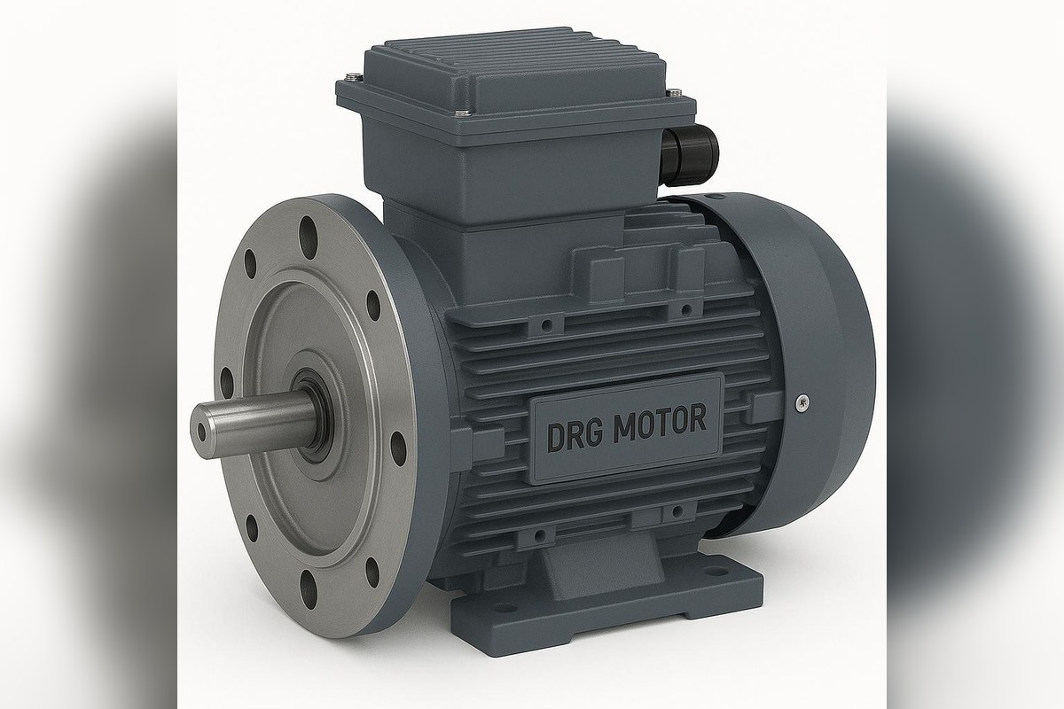

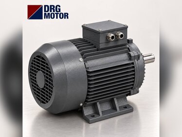
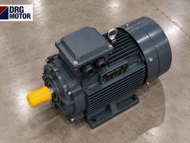
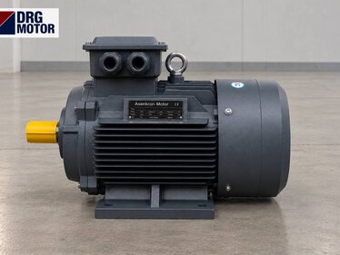
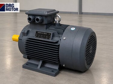
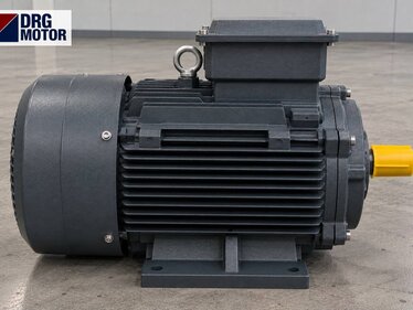
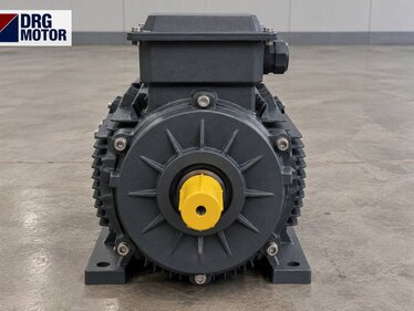
On universal and vertical milling machines the spindle motor is usually a 4-pole three-phase motor of about 1500 rpm, mounted on the vertical head with a downward-facing B5 flange (V1 position); on small and mid-size machines its power is generally in the 1.5–5.5 kW range, and the exact value is on the machine plate or in the maker's data. For example, the 4 kW DRG-112M-4 delivers 26.3 Nm at 1450 rpm and draws 7.95 A at 400 V; the B5 flange of the 112M frame has a 250 mm outside diameter, a 215 mm bolt circle and a 180 mm spigot.
Two things decide the motor on a milling machine: the torque the cutter needs and the flange size the head accepts. Even with enough power, a motor whose spigot does not match will not seat on the head. Table feed is handled on most machines by a separate and much smaller motor, and the two should not be mixed up in the same list. Wiring and protection settings must be done by a qualified electrician. All flange- and foot-mounted models are listed by power and speed among the 120 models in our online store.
How Many Motors Does a Milling Machine Have? Spindle and Table Feed
A conventional knee-type mill has at least two drives. The first is the spindle (main) motor: it turns the cutter and supplies almost all of the cutting power. The second is the table feed motor: it moves the table in X and Y and the knee in Z through lead screws and a gearbox. Some machines also have a third, very small motor for the coolant pump.
On a vertical mill the spindle motor sits on top of the head with its shaft pointing down. On horizontal and universal mills the motor is mostly inside or behind the column, foot- or flange-mounted to the gearbox. When replacing a failed motor, first be clear which motor it is: a feed motor with 0.37 kW on its plate and a 4 kW spindle motor do not come from the same frame family.
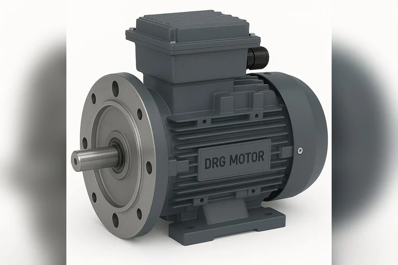
Spindle Motor Power and Torque: P = T · n / 9550
On a mill it is practical to estimate power from the metal removal rate. Volume is Q = ap · ae · vf (cm³/min), where ap is the depth of cut, ae the width of cut and vf the table feed rate. Cutting power is roughly Pc = Q · kc / 60000 (kW, with Q in cm³/min and kc in N/mm²). Once the power is known, spindle torque follows from P = T · n / 9550: T = 9550 · P / n.
Example with assumptions: face milling steel with a Ø63 mm cutter at ap = 4 mm, ae = 50 mm, vf = 400 mm/min, specific cutting force kc = 2000 N/mm² (rounded value), cutting speed vc = 150 m/min. This gives Q = 80 cm³/min and Pc ≈ 2.67 kW. Adding a × 1.25 margin for belt, gear and bearing losses and interrupted cutting brings motor power to about 3.33 kW; the next standard size up is 4 kW.
Cutter speed is n = vc · 1000 / (π · D) ≈ 758 rpm, and at this speed 2.67 kW requires about 33.6 Nm at the spindle. The rated torque of the DRG-112M-4 is 26.3 Nm; with the motor at 1450 rpm and the spindle at 758 rpm the ratio is about 1.91, giving about 50.3 Nm at the spindle, losses excluded. In this example both motor and transmission are adequate.
If you want to run a Ø125 mm cutter at 100 m/min on the same machine, speed drops to about 255 rpm and the required ratio rises to 5.69. That ratio is hard to get from a belt in a single step, which is why a gear step exists for low speeds. You can check ratio and output torque with the gearbox output speed and torque calculator.
Flange Mounting on a Vertical Head: V1 Position and B5 Flange Dimensions
A motor fitted to a vertical head is carried by its flange, not by its frame. Using the large B5 flange vertically with the shaft pointing down is called V1. For the flange to seat on the head, three dimensions must match exactly: spigot (pilot) diameter N, bolt circle diameter M and flange outside diameter P. Hole diameter S sets the bolt size, and spigot length T sets how far the flange enters the recess in the head.
| Frame | M (mm) | N (mm) | P (mm) | S (mm) | T (mm) | LA (mm) | Shaft D × E (mm) |
|---|---|---|---|---|---|---|---|
| 90S / 90L | 165 | 130 | 200 | 12 | 3.5 | 12 | 24 × 50 |
| 100L | 215 | 180 | 250 | 14.5 | 4 | 13 | 28 × 60 |
| 112M | 215 | 180 | 250 | 14.5 | 4 | 14 | 28 × 60 |
| 132S / 132M | 265 | 230 | 300 | 14.5 | 4 | 14 | 38 × 80 |
As the table shows, the 100L and 112M frames share the same flange and the same 28 × 60 mm shaft. On a mill whose head was machined for a 100L motor, moving from 3 kW to 4 kW is therefore possible as far as the flange is concerned; what changes is frame length and weight. Going from a 90 frame to 100L, however, enlarges both flange and shaft, so the head needs an adapter flange or a new coupling. For more detail on flange selection see choosing a flange motor for a gearbox; dimensioned drawings are on the technical drawings page.
What to Watch on a Vertically Running Motor
With the shaft pointing down, the bearings carry the rotor weight axially; coupling alignment, not belt tension, is decisive. The coupling or gear hub on the head must not be hammered onto the shaft; pull it on using the threaded hole in the shaft end. As coolant and chips run downwards, the top of the motor, i.e. the fan cover and terminal box, is where most dirt collects.
- State in the order that the mounting will be B5 and vertical (V1, shaft down).
- Measure the spigot recess in the head against dimension N with a caliper and compare it with the old flange.
- Check bolt circle M and bolt size S; on the 112M frame M = 215 mm and S = 14.5 mm.
- Compare shaft length E with the depth of the coupling hub on the head; if the shaft is too short the key will not carry fully.
- Choose the terminal box orientation to suit the cable route on the head, with the cable gland facing down.
- Keep the top of the fan cover clear of chip build-up; if you add a guard sheet, do not block the air inlet.
- Set the overload relay to the plate current; find the values with the overload, fuse and contactor selection tool.
Table Feed Motor: Why Small and How to Size It?
Table feed means low speed and moderate force. Power is P = F · v. Example with assumptions: feed force 3000 N, feed rate 2 m/min. The mechanical power is then 3000 × 2 / 60 = 100 W. Lead screw, gearbox and slideway friction multiply this value several times; allowing a factor of 3 for losses brings the requirement to about 0.3 kW, and a 0.37 kW motor looks sufficient. On machines with rapid traverse this value can rise, which is why feed motors are generally seen between 0.25 and 1.1 kW; the exact value is again on the plate.
The feed motor reverses often and runs in short on-off cycles. For this reason contactor and overload selection matter more than the motor itself. At small power a 4-pole aluminium frame is light and sufficient; for example the DRG-712-4 is 0.37 kW, 1340 rpm, 0.92 A at 400 V, and the DRG-802-4 is 0.75 kW, 1420 rpm, 1.75 A at 400 V.
Milling with a Frequency Inverter: Speed Setting and Torque Limit
An inverter on the mill spindle makes it easy to choose speed by cutter diameter without changing belts. With small end mills it is tempting to push the speed above 50 Hz; above rated speed, however, the motor enters the constant-power region and torque falls in inverse proportion to speed. At low speed, in the constant-torque region, power falls instead: at the low speed a large cutter needs, the power the motor can deliver stays below its plate value. Keeping at least one low gear step on an inverter-driven machine therefore secures enough torque at the spindle. You can see torque and power versus frequency with the VFD frequency-torque-power calculator.
Which DRG Motor Should I Buy? Model Table for Milling Machines
4-pole cast iron models suit the spindle, small aluminium models suit the table feed. Match the row to the power, speed and flange dimension on the plate.
| Model | Use | Power (kW) | Rated speed (rpm) | Frame | Current 400 V (A) | Torque (Nm) | Flange P / N (mm) |
|---|---|---|---|---|---|---|---|
| DRG-712-4 | Table feed | 0.37 | 1340 | 71 | 0.92 | 2.64 | 160 / 110 |
| DRG-802-4 | Table feed | 0.75 | 1420 | 80 | 1.75 | 5.04 | 200 / 130 |
| DRG-90L-4 | Spindle | 1.5 | 1445 | 90L | 3.3 | 9.91 | 200 / 130 |
| DRG-100L2-4 | Spindle | 3 | 1450 | 100L | 6.02 | 19.8 | 250 / 180 |
| DRG-112M-4 | Spindle | 4 | 1450 | 112M | 7.95 | 26.3 | 250 / 180 |
| DRG-132S-4 | Spindle | 5.5 | 1460 | 132S | 10.7 | 36.0 | 300 / 230 |
Motors in This Power Range
- DRG-712-4 – 0.37 kW – 1340 rpm – 71
- DRG-90L-4 – 1.5 kW – 1445 rpm – 90L
- DRG-100L2-4 – 3 kW – 1450 rpm – 100L
- DRG-112M-4 – 4 kW – 1450 rpm – 112M
- DRG-132S-4 – 5.5 kW – 1460 rpm – 132S
Click to see current prices and order these motors nowSEE PRICES →
Frequently Asked Questions
How many kW should a milling machine motor be?
On small and mid-size vertical mills the spindle motor is generally seen in the 1.5–5.5 kW range; the exact value is the machine plate. On a machine with an unreadable plate, run the removal-rate calculation above and assess it together with the flange size of the head.
Which flange does a vertical mill motor use?
Mostly the large B5 flange in the V1 position, shaft pointing down. Spigot diameter N, bolt circle M and outside diameter P must match the recess in the head exactly; on the 100L and 112M frames, for example, these are 180, 215 and 250 mm.
How many amps does a 4 kW milling motor draw?
The 4 kW, 1500 rpm DRG-112M-4 draws 7.95 A at 400 V and 8.37 A at 380 V at full load. It is delta-connected on a 400 V supply; starting current is around 7.8 times rated current.
Can the table feed motor and the spindle motor be the same?
They have separate mechanical tasks and very different powers. On most machines the table feed motor stays below 1 kW while the spindle motor is several kW. On older single-motor machines the feed is taken from the spindle gearbox; in that case the motor is sized for spindle power.
Send us the flange dimensions of your milling head and the motor plate, and we will choose the right motor together: +90 (542) 666 11 11, [email protected] or our contact page. For all models see Buy Electric Motors Online.