English
 Le français
 Türkçe




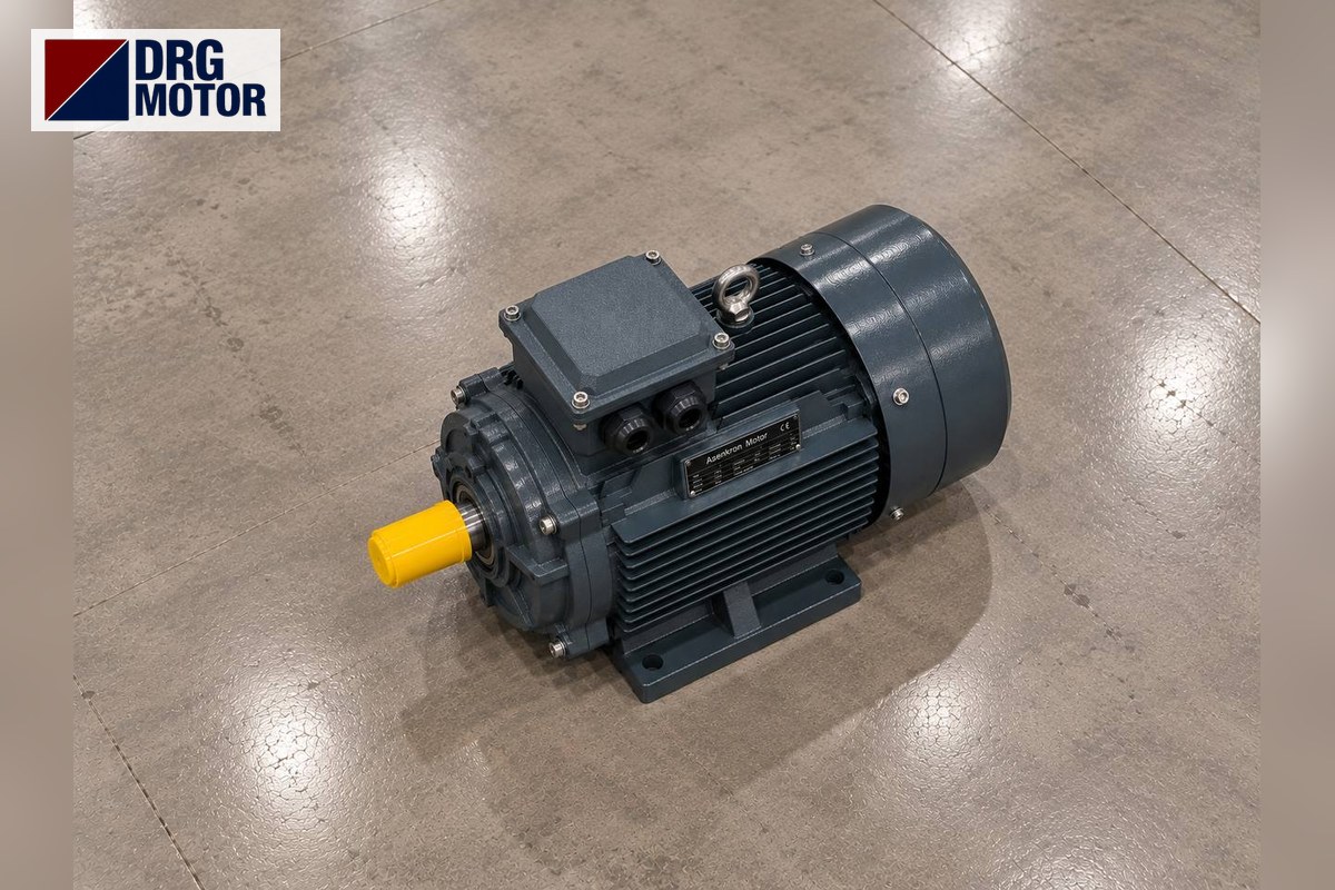

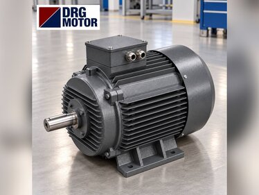
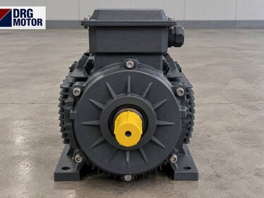
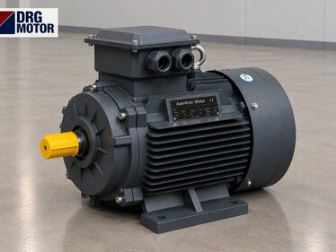
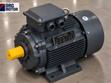
When replacing the hydraulic pump motor of a plastic injection moulding machine, the new motor is matched to four items on the old motor’s nameplate: power, speed (number of poles), IEC frame and mounting arrangement. For example, a pump motor whose plate reads 15 kW, 1460 rpm and 160L is replaced by DRG-160L-4: 15 kW, 1465 rpm, frame 160L, 42 × 110 mm shaft; it draws 27.3 A at 400 V and is delta-connected. Because the frame stays the same, the pump bell housing, coupling half and base holes are reused unchanged. The machine builder’s nameplate value should be the basis; increasing power is justified only by calculation.
The general framework of motor selection on injection machines (differences between hydraulic, hybrid and all-electric machines) is covered in our article Electric Motor Selection for Plastic Injection Machines; this article focuses only on replacing a failed or undersized pump motor. Removal, connection and overload setting must be done by a qualified electrician. The 4-pole models used as pump motors are listed by power and frame on Buy Electric Motors Online.
Matching the New Motor from the Old Nameplate
If the plate is legible, the job is easy. The table below compares an example 15 kW pump motor nameplate with its DRG equivalent line by line:
| Nameplate item | Example old motor | DRG-160L-4 | Match |
|---|---|---|---|
| Power | 15 kW | 15 kW | same |
| Speed | 1460 rpm | 1465 rpm | 4-pole, same |
| Frame | 160L | 160L | same |
| Shaft D × E | 42 × 110 mm | 42 × 110 mm | coupling reused |
| Connection 400 V | Δ (delta) | Δ (delta) | star-delta suitable |
| Mounting | B35 | B35 (on order) | flange + feet |
If the plate is unreadable, three measurements identify the frame: shaft diameter D, shaft centre height H (on foot-mounted motors) and the flange spigot diameter N. For example, a 42 mm shaft, 160 mm shaft height and 250 mm spigot point to frame 160; to tell 160M from 160L, measure the foot hole spacing B (210 and 254 mm). All frame dimensions are on the DRG motor technical drawings page.
Coupling to the Pump: Bell Housing, Coupling, B5 and B35
In a hydraulic power unit the motor is connected to the pump through a bell housing, with a flexible coupling between motor shaft and pump shaft. Two mounting arrangements are seen on the motor side:
- B5 (flange only): The motor hangs on the bell housing with no feet. Common on small and medium units sitting vertically or horizontally on the tank.
- B35 (feet + flange): The motor is fixed both to the bell housing and to the base. Preferred on larger frames so that the bell housing does not carry the motor weight. During replacement, tighten the foot bolts last so they do not pull the bell housing out of line.
The motor side of the bell housing is machined to the B5 flange dimensions. Catalogue values for the frames concerned:
| Frame | B5 flange P / N / M | Hole S / spigot T | Key F |
|---|---|---|---|
| 132M | 300 / 230 / 265 mm | 14.5 / 4 mm | 10 mm |
| 160M | 350 / 250 / 300 mm | 18.5 / 5 mm | 12 mm |
| 160L | 350 / 250 / 300 mm | 18.5 / 5 mm | 12 mm |
| 180M | 350 / 250 / 300 mm | 18.5 / 5 mm | 14 mm |
| 180L | 350 / 250 / 300 mm | 18.5 / 5 mm | 14 mm |
Frames 160M, 160L, 180M and 180L share the same flange (P 350, N 250, M 300 mm), but the shaft is 42 mm on 160 and 48 mm on 180. So when going from 15 kW to 18.5 kW the bell housing can stay, but the motor half of the coupling must be rebored or replaced. Going from 132M to 160M changes both bell housing and coupling.
Shaft D × E Fit and Coupling Alignment
The coupling hub is machined to shaft diameter D and key width F; hub length must not exceed shaft length E. On frame 160 the shaft is 42 × 110 mm with a 12 mm key, on frame 180 it is 48 × 110 mm with a 14 mm key. Points to watch during assembly:
- The axial gap between coupling halves must match the coupling maker’s value; the motor shaft must not butt against the pump shaft.
- The bell housing spigot (N) keeps misalignment small, but on B35 wrong foot shims make the motor strain the bell housing.
- If the old coupling spider is hardened or torn, replace it with the motor; a worn insert returns to the new motor’s bearing as shock.
- The key must sit tightly in its slot and must not protrude from the hub.
Power Check: a P = Q · p / 600 / η Example
If raising or lowering power is being considered at replacement, the peak hydraulic power is calculated: P (kW) = Q (L/min) × p (bar) / 600 / η. Assumed example: the pump delivers 60 L/min, injection pressure is 140 bar, pump efficiency η = 0.85. P = 60 × 140 / 600 / 0.85 ≈ 16.5 kW. This peak is above 15 kW, but the injection phase lasts only a few seconds. At this peak the 15 kW DRG-160L-4 delivers 9550 × 16.47 / 1465 ≈ 107.4 Nm: about 1.1 times its rated torque (97.8 Nm) and less than half its breakdown torque (2.3 × 97.8 ≈ 224.9 Nm). This short overshoot is acceptable; what really decides is the cycle heating calculated below. With your own flow and pressure values you can use the pump and fan motor power calculator.
Heating in Frequent Load-Idle Cycles: Equivalent Power
An injection machine swings between pressurised phases and low load in every cycle. Motor heating relates not to peak power but to the time average of power squared (root mean square). Example 23-second cycle (η = 0.85, assumed pump efficiency):
| Phase | Time | Flow × pressure | Hydraulic power / η |
|---|---|---|---|
| Mould closing | 2 s | 60 L/min × 40 bar | 4.71 kW |
| Injection | 3 s | 60 L/min × 140 bar | 16.47 kW |
| Holding pressure | 5 s | 15 L/min × 100 bar | 2.94 kW |
| Dosing (plasticising) | 10 s | 40 L/min × 120 bar | 9.41 kW |
| Opening + ejector | 3 s | 60 L/min × 40 bar | 4.71 kW |
Equivalent power is √[(4.71² × 2 + 16.47² × 3 + 2.94² × 5 + 9.41² × 10 + 4.71² × 3) / 23] ≈ 9.0 kW. A 15 kW motor is thermally comfortable in this cycle. If the old motor still ran hot, the cause is usually not power but one of the following:
- The pressure relief valve is set higher than necessary, so the pump works under pressure even while idling.
- The hydraulic oil is hot; the oil cooler is dirty or water flow is insufficient.
- The motor fan or fan cover is clogged with dust and the frame fins are dirty.
- Phase currents are unbalanced; a terminal is loose on one phase.
Checking these before replacement keeps the new motor from heating up for the same reason.
Commissioning Checklist after Replacement
- Direction of rotation: does it follow the arrow on the pump body? Check with a brief jog; a gear or vane pump running backwards can be damaged within seconds.
- Connection: store motors of 4 kW and above are 400/690 V, run in delta on a 400 V supply and suit star-delta starting; the pump must start unloaded (unloading valve open).
- Overload setting: to nameplate current (27.3 A at 400 V for DRG-160L-4); see the overload, fuse and contactor selection tool.
- Measure and record current on each phase during the first hour; idle-circulation current is a reference for future fault diagnosis.
- Are the coupling guard and bell housing ventilation openings in place?
- Check the motor frame by hand, and with a thermometer if possible, at the end of the first shift.
Injection Pump Motor Model Table
Pump motor ratings common on small and medium tonnage hydraulic injection machines (4-pole, cast iron, current at 400 V full load):
| Model | Power / speed | Frame, shaft D×E | Current 400 V |
|---|---|---|---|
| DRG-132M-4 | 7.5 kW / 1460 rpm | 132M, 38 × 80 mm | 14.3 A |
| DRG-160M-4 | 11 kW / 1465 rpm | 160M, 42 × 110 mm | 20.4 A |
| DRG-160L-4 | 15 kW / 1465 rpm | 160L, 42 × 110 mm | 27.3 A |
| DRG-180M-4 | 18.5 kW / 1470 rpm | 180M, 48 × 110 mm | 33.5 A |
| DRG-180L-4 | 22 kW / 1470 rpm | 180L, 48 × 110 mm | 39.7 A |
Pump Motors in This Power Range
- DRG-132M-4 – 7.5 kW – 1460 rpm – 132M
- DRG-160M-4 – 11 kW – 1465 rpm – 160M
- DRG-160L-4 – 15 kW – 1465 rpm – 160L
- DRG-180M-4 – 18.5 kW – 1470 rpm – 180M
- DRG-180L-4 – 22 kW – 1470 rpm – 180L
Click to see current prices and order these motors nowSEE PRICES →
Frequently Asked Questions
How many kW is an injection machine pump motor?
It depends on the machine’s tonnage and pump flow; 7.5–22 kW is common on small and medium machines. The definitive value is the machine nameplate or the builder’s data; without a plate, calculate peak power with Q × p / 600 / η and equivalent power with a cycle table.
Does the coupling change when the pump motor is replaced?
Not if the frame is the same. Going from frame 160 to 180 keeps the flange, but the shaft grows from 42 mm to 48 mm, so the motor half of the coupling changes.
How many amps does a 15 kW pump motor draw?
The 15 kW, 1500 rpm DRG-160L-4 draws 27.3 A at full load on 400 V and 28.8 A on 380 V. Starting current is about 7.8 times rated current, which is why star-delta starting is common.
Why does an injection pump motor overheat?
Usually the cause is on the hydraulic side, not the motor: a relief valve set too high, hot oil, a dirty cooler. A clogged fan cover and unbalanced phase currents also cause heating. Check these before replacement.
Send us a photo of your old motor’s nameplate and the pump details, and let us find its exact equivalent together: +90 (542) 666 11 11, [email protected] or our contact page. All models: Buy Electric Motors Online.