English
 Le français
 Türkçe




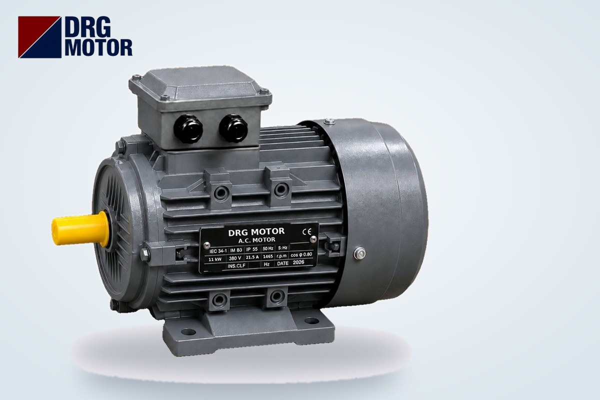

A motor is earthed by connecting the green-yellow protective conductor (PE) of the supply cable with a crimped lug to the earth screw marked ⏚ inside the terminal box, so that this conductor reaches the installation's earthing system via the PE bar in the panel. On motors that also have an external earth screw on the frame, that screw is an additional connection point for the machine frame or an equipotential bonding conductor; it does not replace the PE in the cable. The PE cross-section depends on the phase conductor cross-section: up to 16 mm² it is the same as the phase conductor.
Earthing is a life-safety connection; isolating and locking off the motor, making the connection and measuring it afterwards is a job for a qualified electrician. The earth resistance of the installation, residual current protection and the cross-section calculation are the responsibility of an electrical engineer. This article explains step by step what the person wiring the motor on site must pay attention to; it does not replace the calculation required by regulations.
The current and cable entry values in the examples are catalogue data for the three-phase motors in our Buy Electric Motors Online section; the cross-section examples come from the table of our cable size tool (copper, PVC, about 30 °C).
Why Is a Motor Earthed? Touch Voltage and the RCD
If the winding insulation breaks down because of moisture, vibration, overheating or a cable crushed in the terminal box, phase voltage reaches the motor frame. If the frame is not earthed, the motor keeps running and no protective device notices; a person touching the frame becomes the current's path to earth. Earthing provides that path in advance and with a much lower resistance. Depending on the type of supply system, the result is as follows:
- When the fault current is high (the frame is connected through PE to the earthed point of the source), the fault effectively becomes a short circuit; the fuse or motor protection circuit breaker opens the circuit.
- A residual current device (RCD) measures the difference between outgoing and returning current. If the frame is earthed, the fault current flows through PE immediately and the RCD trips before anyone touches the frame. If the frame is not earthed, the RCD only operates once current flows through a person; protection comes late.
- Touch voltage is the voltage between the frame and the floor you are standing on during a fault. The sounder and lower-resistance the PE connection, the lower this voltage stays.
We covered the general importance of earthing in our article why electric motor grounding matters; here we focus on the practical side.
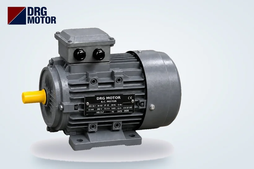
Where Is the Earth Screw? Inside the Terminal Box and on the Frame
Three-phase motors have two possible earthing points, each with a different role:
| Point | Location | What is connected | Mandatory? |
|---|---|---|---|
| Internal earth screw | Inside the terminal box next to the terminal block; marked ⏚ or PE | Green-yellow PE core of the supply cable | Yes, on every motor |
| External earth screw | On the frame or foot (if fitted) | Equipotential bonding conductor, machine frame connection | Depends on installation design; does not replace the internal connection |
| Cable screen (drive systems) | EMC cable gland or screen clamp in the terminal box | Braid of the screened cable | Required with a drive |
Connecting PE to the terminal box cover or its bolt is wrong; the connection is lost when the cover is removed. Seating a lug directly on a painted surface also raises contact resistance. PE must go to the screw provided on the motor for this purpose.
Motor Earth Connection Step by Step
- Isolate, lock off, tag. Switch off the panel isolator, fit a lock and tag, and confirm with a suitable tester that there is no voltage at the motor terminals.
- Pass the cable through the gland. Use a gland matching the motor's cable entry size (example: 1 × M25×1.5 for the 1.5 kW 4-pole DRG-90L-4; 2 × M40×1.5 for the 11 kW DRG-160M-4).
- Leave the PE core slightly longer than the phase cores. If the cable is pulled or the gland loosens, the phase conductors must break first and the PE last.
- Crimp a suitable lug. Crimp a round (ring) lug matching the core size and screw diameter with a crimping tool suited to the cross-section. Fork lugs are avoided because they can slip out when loose.
- Connect to the earth screw. Seat the lug between the screw's washer and the surface and tighten as specified by the manufacturer. If more than one lug must go under the same screw, keep the order and washers as intended.
- Connect the phase conductors. PE first, then L1 L2 L3; the reverse when disconnecting.
- Connect the external screw (if any). If equipotential bonding is specified for the installation, connect the relevant conductor to the external screw on the frame.
- Measure, then energise. The motor is not started before continuity and insulation have been measured (see below).
What Size Should the Earth Cable Be? PE Size Depends on Phase Size
Turkey's Regulation on Earthing in Electrical Installations allows two routes for the protective conductor: calculation from the short-circuit current and the disconnection time of the protective device (S = √(I²·t) / k), or a minimum cross-section table based on the phase conductor (Table 8). The table applies when the PE is made of the same material as the phase conductor:
| Phase conductor cross-section S | Minimum protective conductor (PE) cross-section |
|---|---|
| S ≤ 16 mm² | S (same as phase) |
| 16 mm² < S ≤ 35 mm² | 16 mm² |
| S > 35 mm² | S / 2 (next standard size if not a standard value) |
According to the regulation, a separate PE that is not part of the supply cable may not be smaller than 2.5 mm² with mechanical protection or 4 mm² without. In standard four-core and five-core cables the PE core already has the same cross-section as the phase cores; a separate PE only comes into play with large cross-sections or single-core cables.
Example: from motor current to PE size
In the table below, the 380 V current of 4-pole (1500 rpm) motors is multiplied by 1.25 to give the design current, the smallest copper cross-section carrying that current is taken from our cable size tool's table, and the PE size is given according to the rule above. This is the current-carrying criterion only; voltage drop on long runs, installation method, grouping and ambient temperature may require a larger size. The final cross-section must be confirmed by an electrical engineer.
| Model | Power | Current at 380 V | Design current (×1.25) | Phase size (current capacity) | Minimum PE size | Cable entry |
|---|---|---|---|---|---|---|
| DRG-90L-4 | 1.5 kW | 3.47 A | ≈ 4.34 A | 1.5 mm² (18.5 A) | 1.5 mm² | 1 × M25×1.5 |
| DRG-160M-4 | 11 kW | 21.5 A | ≈ 26.9 A | 4 mm² (34 A) | 4 mm² | 2 × M40×1.5 |
| DRG-225S-4 | 37 kW | 69.6 A | 87 A | 25 mm² (101 A) | 16 mm² | 2 × M50×1.5 |
| DRG-280S-4 | 75 kW | 136 A | 170 A | 70 mm² (196 A) | 35 mm² | 2 × M63×1.5 |
| DRG-315L1-4 | 160 kW | 285 A | ≈ 356 A | 185 mm² (364 A) | 92.5 → 95 mm² | 2 × M63×1.5 |
In the 160 kW row, S/2 = 92.5 mm² is not a standard size, so the next standard value, 95 mm², is given. To calculate the size together with cable length, use our motor cable size calculator; for choosing protective devices, use the overload relay, fuse and contactor selection tool.
Screened Cable and Screen Earthing on Drive-Fed Motors
A frequency drive feeds the motor with fast-switched voltage pulses. These pulses create high-frequency leakage currents through the capacitance between the cable and earth; current that finds no proper path flows through the bearings, the machine frame or nearby signal cables. In a drive system, earthing is therefore not only a safety issue but also a matter of electromagnetic compatibility:
- A screened (shielded) motor cable is used between drive and motor; the cable also contains a PE core.
- The screen braid is connected at the motor end with an EMC gland giving 360° contact to the terminal box, and at the drive end with the drive's screen clamp. Twisting the braid into a thin "pigtail" and screwing it down largely destroys its effect at high frequency.
- Whether the screen is connected at both ends and the maximum cable length are specified in the drive manufacturer's installation manual; follow that manual.
- The motor frame, the drive's PE terminal and the machine frame should reach the same earthing point via short, heavy connections.
How Is Earthing Measured? Continuity, Insulation and Earth Resistance
Having the connection "in place" is not enough; it must be verified by measurement. There are three separate measurements on site, all carried out by a qualified electrician with suitable instruments:
- Continuity test: with the power off, the resistance between the motor frame and the PE bar in the panel is measured with a low-resistance ohmmeter. Broken, loose or oxidised connections show up here.
- Insulation resistance test: measured between windings and frame with an insulation tester (megger); it shows the health of the winding rather than the earthing, but it is the way to find out whether there is leakage to the frame without energising. Drives and electronic devices must be disconnected during the test.
- Earth resistance / fault loop impedance: shows whether the installation's earth electrode and the fault path will make the protective device trip in time. Acceptance values depend on the supply system type and the protective device; this measurement is part of periodic inspection and is reported.
Common Mistakes in Motor Earthing
- Connecting PE to neutral: a three-phase motor needs no neutral; connecting the neutral conductor to the frame turns the frame into a conductor carrying operating current.
- Relying only on the feet for earthing: the frame the motor is bolted to or a concrete base does not count as a protective conductor; paint, rust and vibration spoil the contact.
- Using the green-yellow core as a phase, or using a core of another colour as PE: this creates a potentially fatal error at the next maintenance.
- Clamping a solder-tinned end directly under the screw: solder creeps over time and the connection loosens; use a lug.
- Forgetting to reconnect PE when replacing a motor: the PE disconnected from the old motor should be the first conductor connected to the new one.
- Cutting off the screen in a drive system: leakage currents find a path through bearings and signal lines.
- Reducing the size "by eye": for phase sizes up to 16 mm², PE may not be smaller than the phase conductor.
Post-connection checklist
- Is PE on the ⏚ screw inside the terminal box, with a ring lug, and tight?
- Was the PE core left longer than the phase cores?
- Is the PE size adequate for the phase size (equal up to 16 mm²)?
- Does the cable gland match the motor's cable entry size, and is it tight?
- Has continuity been measured between the frame and the panel PE bar?
- Has the winding-to-frame insulation resistance been measured?
- In a drive system, is the screen connected at both ends as the manual requires?
- Is the external earth screw connected (if fitted and specified in the design)?
- Have the terminal box gasket and cover been refitted?
Three-Phase Motors Used in the Examples
The models used in the cross-section and cable entry examples above:
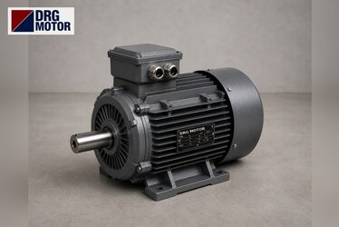
- DRG-90L-4 – 1.5 kW – 1500 rpm – aluminium frame, IEC 90L
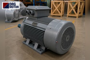
- DRG-160M-4 – 11 kW – 1500 rpm – cast iron frame, IEC 160M
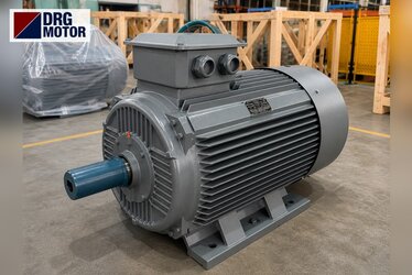
- DRG-225S-4 – 37 kW – 1500 rpm – cast iron frame, IEC 225S
- DRG-280S-4 – 75 kW – 1500 rpm – cast iron frame, IEC 280S
- DRG-315L1-4 – 160 kW – 1500 rpm – cast iron frame, IEC 315L
Click to see current prices and order these motors nowSEE PRICES →
Frequently Asked Questions
Where is the motor earth wire connected?
The green-yellow PE core of the supply cable is connected with a ring lug to the earth screw marked ⏚ inside the terminal box; the other end of the core goes to the PE bar in the panel. An external screw on the frame, if present, is for equipotential bonding and does not replace this connection.
What size should a motor earth cable be?
If the phase conductor is up to 16 mm², PE is the same size; between 16 and 35 mm² it is 16 mm², and above 35 mm² it is half the phase size. For example, on an 11 kW 4-pole motor the phase size by current capacity is 4 mm², so PE is also 4 mm². The exact value is confirmed by an electrical engineer against the installation's short-circuit conditions.
Does an RCD trip if there is no earth?
Yes, but late: if the frame is not earthed, fault current only flows when someone touches the frame and current passes through them to earth. Earthing makes the RCD trip before anyone touches it. An RCD does not replace earthing; it works together with it.
The motor frame gives an electric shock; what could be the cause?
Usually a broken or missing PE connection combined with an insulation fault in the winding, terminal box or cable. De-energise the motor immediately and do not restart it until an electrician has measured continuity and insulation. In drive systems, a slight tingle may indicate a faulty screen and earthing arrangement.
If you have questions about motor selection or cable entry sizes, contact us: +90 (542) 666 11 11, [email protected] or our contact page. For the technical data of every model, browse the 120 models in our online store.