English
 Le français
 Türkçe




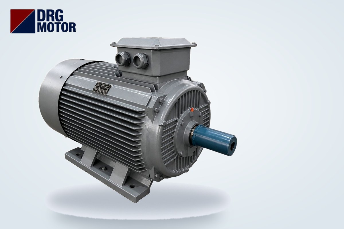

A 200 kW, 1500 rpm (4-pole) three-phase motor draws about 352 A at full load on a 380 V supply, and a 250 kW, 1500 rpm motor draws about 440 A; at 400 V these values fall to 334 A and 418 A. The pole count shifts the current by a few amps: at 200 kW the 2-pole model draws 349 A and the 6-pole 365 A; at 250 kW the 2-pole draws 436 A and the 6-pole 456 A. These are the nameplate currents of the cast iron 315L and 355 frame models in our Buy Electric Motors Online store.
At this power level the real question does not stop at "how many amps". A 250 kW motor needs roughly 290 kVA of apparent power while running and momentarily more than 2,000 kVA during a direct-on-line start. Transformer rating, the current level of the main panel breaker, single versus parallel cables and the need for power factor correction are all derived from these two values. For the final design, the plant's electrical engineer, the transformer manufacturer and the distribution company's requirements are decisive.
200 and 250 kW Motor Current Table: 2, 4 and 6 Poles
The 380 V and 400 V currents in the table are nameplate values from the data sheet. The 690 V column is calculated with I ∝ 1/U, using the fact that the motor is rated 400/690 V (Δ/Y) (400 V current × 400 / 690). All six models are connected in delta (Δ) on a 380 V network and have 2 × M63×1.5 cable entries on the terminal box.
| Model | Power | Poles / rated speed | IEC frame | cos φ | Current 380 V | Current 400 V | Current 690 V (Y, calculated) | Is/In | Rated torque | Store |
|---|---|---|---|---|---|---|---|---|---|---|
| DRG-315L2-2 | 200 kW | 2-pole / 2,980 rpm | 315L | 0.91 | 349 A | 331 A | 192 A | 7.2 | 640.9 Nm | See Prices |
| DRG-315L2-4 | 200 kW | 4-pole / 1,490 rpm | 315L | 0.90 | 352 A | 334 A | 194 A | 7.1 | 1,282 Nm | See Prices |
| DRG-355M2-6 | 200 kW | 6-pole / 990 rpm | 355M | 0.87 | 365 A | 346 A | 201 A | 6.8 | 1,929 Nm | See Prices |
| DRG-355M-2 | 250 kW | 2-pole / 2,982 rpm | 355M | 0.91 | 436 A | 414 A | 240 A | 7.2 | 800.6 Nm | See Prices |
| DRG-355M-4 | 250 kW | 4-pole / 1,490 rpm | 355M | 0.90 | 440 A | 418 A | 242 A | 7.1 | 1,602 Nm | See Prices |
| DRG-355L-6 | 250 kW | 6-pole / 990 rpm | 355L | 0.87 | 456 A | 433 A | 251 A | 6.8 | 2,412 Nm | See Prices |
Two practical conclusions follow from the table. First, at the same power, cos φ falls as speed falls (0.91 → 0.90 → 0.87) and current rises; the 6-pole 250 kW motor draws 20 A more than the 2-pole one. Second, torque grows quickly as speed falls: at 250 kW the 2-pole delivers 800.6 Nm while the 6-pole delivers 2,412 Nm. This difference affects the coupling, the shaft (D = 100 mm on the 6-pole) and the base frame calculation. For smaller ratings, see the motor current chart tool.
How Many kVA Does a 200 or 250 kW Motor Draw Running and Starting?
Transformers and generators are rated in kVA, while the motor nameplate shows kW and amps. The bridge formula is: S (kVA) = √3 × U × I / 1000.
While running
250 kW, 4-pole (DRG-355M-4): S = 1.732 × 380 × 440 / 1000 ≈ 290 kVA. 200 kW, 4-pole (DRG-315L2-4): S = 1.732 × 380 × 352 / 1000 ≈ 232 kVA. The difference from the kW rating comes from the reactive component and internal losses.
During starting
Starting current = In × Is/In. For 250 kW, 4-pole: 440 × 7.1 ≈ 3,124 A, corresponding to a momentary power of ≈ 2,056 kVA. With star-delta starting, the current drawn from the network in the star stage drops to about one third of the direct-on-line value: ≈ 1,041 A and ≈ 685 kVA. Comparison of the six models:
| Model | Running S (kVA) | DOL starting current | DOL starting S (kVA) | Star-delta starting current (≈ 1/3) | Star-delta starting S (kVA) |
|---|---|---|---|---|---|
| DRG-315L2-2 | 230 | 2,513 A | 1,654 | 838 A | 551 |
| DRG-315L2-4 | 232 | 2,499 A | 1,645 | 833 A | 548 |
| DRG-355M2-6 | 240 | 2,482 A | 1,634 | 827 A | 545 |
| DRG-355M-2 | 287 | 3,139 A | 2,066 | 1,046 A | 689 |
| DRG-355M-4 | 290 | 3,124 A | 2,056 | 1,041 A | 685 |
| DRG-355L-6 | 300 | 3,101 A | 2,041 | 1,034 A | 680 |
Because torque also falls to about one third, star-delta starting only works when the load is light at start-up (fans, compressors starting unloaded, pumps with a throttled valve). With heavy loads, a soft starter or a frequency drive is considered. To compare methods, use the star-delta and motor starting methods tool.
How to Account for the Motor When Sizing the Transformer
A transformer is sized by considering the plant's total load together with the start of the largest motor. The motor's share is seen through two ratios:
- Running share: on a 1000 kVA transformer, a 250 kW motor (≈ 290 kVA) alone uses about 29% of the rating. On a 630 kVA transformer the share rises to about 46%.
- Starting share: the ≈ 2,056 kVA of a direct-on-line start is about twice the rating of a 1000 kVA transformer. The secondary voltage drops depending on the transformer's short-circuit impedance (uk). With star-delta, ≈ 685 kVA keeps the starting moment below the transformer rating.
The acceptable voltage dip is defined by the transformer manufacturer's data and connection approval by the distribution company's requirements. For generator supply, see our article on supplying a motor from a generator and a transformer.
What Current Level Should the Panel Main Breaker Have?
The moulded case breaker protecting the motor outgoing feeder must carry the running current, must not trip during starting and must protect the cable. For a 250 kW, 4-pole motor:
- The overload setting is based on the motor's In (440 A at 380 V); the setting range should comfortably include 440 A.
- The magnetic (instantaneous) trip threshold must stay above the ≈ 3,124 A direct-on-line starting current and the peak current of the first instant of starting; otherwise the breaker trips at every start.
- The breaker's rated current must not exceed the total current-carrying capacity of the cable selected in the next section.
Since In is 352 A for the 200 kW motor and 440 A for the 250 kW motor, the two ratings often fall into different breaker frame sizes. The general breaker of the main distribution board is sized not for the motor alone but for the sum of all outgoing feeders and the transformer secondary current (≈ 1,443 A at 400 V for 1000 kVA). Take the exact setting from the device manufacturer's selection table; to test the logic, use the overload relay, fuse and contactor selection tool.
Parallel Cable Calculation When 240 mm² Is Not Enough
In the table of our motor cable size calculator (copper, PVC, ~30 °C example values), the largest cross-section is 240 mm² with a current-carrying capacity of 430 A. With a design current of In × 1.25, none of the six models fits a single 240 mm² cable; the solution is two identical cables per phase.
| Model | In (380 V) | Design current In × 1.25 | Single 240 mm² (430 A) enough? | Parallel example (cable table) | Combined rating of two cables |
|---|---|---|---|---|---|
| DRG-315L2-2 | 349 A | 436.2 A | No | 2 × 95 mm² | 476 A |
| DRG-315L2-4 | 352 A | 440.0 A | No | 2 × 95 mm² | 476 A |
| DRG-355M2-6 | 365 A | 456.2 A | No | 2 × 95 mm² | 476 A |
| DRG-355M-2 | 436 A | 545.0 A | No | 2 × 120 mm² | 552 A |
| DRG-355M-4 | 440 A | 550.0 A | No | 2 × 120 mm² | 552 A |
| DRG-355L-6 | 456 A | 570.0 A | No | 2 × 150 mm² | 638 A |
Example: 250 kW, 4-pole → 440 × 1.25 = 550 A. The 120 mm² cable in the table carries 276 A; 2 × 276 = 552 A is borderline. Because it would immediately fall short after grouping and temperature correction, 2 × 150 mm² (638 A) is a safer starting point. Four rules never change for parallel cables: same cross-section, same length, same type and same route; otherwise current is not shared equally between the cables.
Voltage drop (ΔU = √3 × I × L/1000 × R × cos φ; with two parallel cables R is halved) for 250 kW, 4-pole, 440 A and cos φ 0.90:
| Line length | 2 × 120 mm² | 2 × 150 mm² | 2 × 185 mm² |
|---|---|---|---|
| 50 m | 2.62 V (0.69%) | 2.13 V (0.56%) | 1.70 V (0.45%) |
| 100 m | 5.25 V (1.38%) | 4.25 V (1.12%) | 3.40 V (0.89%) |
| 150 m | 7.87 V (2.07%) | 6.38 V (1.68%) | 5.10 V (1.34%) |
Up to 150 m, a 2 × 150 mm² line stays below the 3% supply limit; at this power the cross-section is usually governed by current-carrying capacity. With star-delta starting, two cable sets run from the panel to the motor and each conductor carries the phase current, In/√3 ≈ 254 A (design current ≈ 317 A). All of these values are example calculations; the cross-section must be verified by an electrical engineer according to installation method, grouping and ambient temperature.
Power Factor Correction: Reactive Power of a 200 and 250 kW Motor
Back-calculation from nameplate values: for 250 kW, 4-pole, the active power drawn from the network is P = √3 × 380 × 440 × 0.90 ≈ 261 kW and the reactive power Q = √(S² − P²) ≈ 126 kVAr. The capacitor power needed to raise cos φ from 0.90 to 0.95 is Qc = P × (tan φ1 − tan φ2) ≈ 41 kVAr; the same calculation for 200 kW, 4-pole gives ≈ 33 kVAr. On 6-pole models cos φ is 0.87, so the requirement grows (≈ 62 kVAr at 250 kW).
In practice there are two routes: a central automatic power factor correction panel or fixed capacitors at the motor terminals. If fixed capacitors are chosen, their rating must not exceed the motor's no-load reactive power; otherwise a motor still spinning after a supply loss can self-excite and dangerous voltage can appear at the terminals. For the step plan, use the power factor correction calculator.
Panel and Transformer Planning Checklist for 200–250 kW Motors
- Check the voltage on the nameplate: 400/690 V (Δ/Y) → delta on a 380/400 V network, star on a 690 V network.
- Do not estimate current from kW; take it from the nameplate.
- Calculate running and starting kVA and send them to the transformer manufacturer together with the transformer rating and short-circuit impedance.
- Select the starting method according to the load type; remember that starting torque falls to about one third in star-delta.
- The breaker's setting range should consider In, its instantaneous threshold the starting current, and its rated current the cable capacity.
- If the cross-section exceeds 240 mm², plan parallel cables of equal length; check gland and lug sizes against the 2 × M63×1.5 entries on the terminal box.
- Calculate voltage drop with the actual line length; increase the cross-section on routes exceeding the 3% supply limit.
- Calculate reactive power and plan the correction steps; with fixed capacitors at the motor, respect the no-load reactive power limit.
Motors in This Power Range
- DRG-315L2-2 – 200 kW – 3000 rpm – 315L cast iron
- DRG-315L2-4 – 200 kW – 1500 rpm – 315L cast iron
- DRG-355M2-6 – 200 kW – 1000 rpm – 355M cast iron
- DRG-355M-2 – 250 kW – 3000 rpm – 355M cast iron
- DRG-355M-4 – 250 kW – 1500 rpm – 355M cast iron
- DRG-355L-6 – 250 kW – 1000 rpm – 355L cast iron
Click to see current prices and order these motors nowSEE PRICES →
Frequently Asked Questions
How many amps does a 250 kW motor draw?
A 250 kW, 1500 rpm motor draws about 440 A at 380 V and 418 A at 400 V. The 3000 rpm model draws 436 A at 380 V and the 1000 rpm model 456 A. Connected in star on a 690 V network, the 4-pole model's current drops to about 242 A.
What size transformer (kVA) does a 200 kW motor need?
A 200 kW, 4-pole motor draws about 232 kVA while running, a momentary ≈ 1,645 kVA during direct-on-line starting and ≈ 548 kVA with star-delta. The transformer rating is determined by adding the plant's other loads to these values; the voltage dip during starting depends on the transformer's short-circuit impedance. The transformer manufacturer's and distribution company's requirements govern the final choice.
What cable size is needed for a 250 kW motor?
In the example calculation the design current is 440 × 1.25 = 550 A, and a single 240 mm² cable (430 A) is not enough. According to the site's table, 2 × 120 mm² per phase is borderline (552 A) and 2 × 150 mm² (638 A) is a safer starting point. An electrical engineer must verify the cross-section for the installation method and grouping.
Can a 250 kW motor be started direct-on-line?
Technically the motor withstands a direct start, but the ≈ 3,124 A starting current and ≈ 2,056 kVA momentary power cause a serious voltage dip on most plant transformers. At this power, star-delta, a soft starter or a frequency drive is generally preferred; the decision depends on the load type and the distribution company's requirements.
To select a motor that fits the transformer, panel and cable plan of your project, call us on +90 (542) 666 11 11, write to [email protected] or use our contact page. You can browse every rating from 0.25 kW to 355 kW among the 120 models in our online store.