English
 Le français
 Türkçe




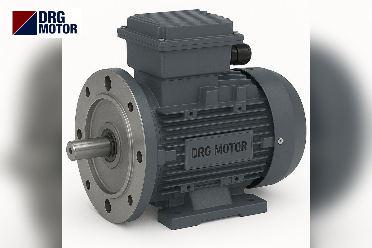

The 4 kW motor most often used on hydraulic power units is the 4-pole DRG-112M-4, which bolts to the pump lantern with the B5 flange of the 112M frame: spigot 180 mm, bolt circle 215 mm, outside diameter 250 mm, shaft 28×60 mm. The 2-pole DRG-112M-2 uses the same flange and shaft; the 6-pole DRG-132M1-6 moves up to the 132M frame and needs a lantern that accepts a 230 mm spigot, 265 mm bolt circle and 38×80 mm shaft.
If the lantern and coupling already exist, first check which of these sizes they are machined to; the motor choice then follows almost by itself. The aluminium and cast iron versions of the 4 kW models are listed on the Buy Electric Motors Online page.
4 kW is the first power in the DRG catalogue where the winding changes to 400/690 V: all three models are delta (Δ) connected on a 380 V supply. This allows the star-delta starting often used on hydraulic units; details below. Panel work must be done by a qualified electrician.
Dimensions for the pump lantern and coupling
On a hydraulic unit the motor is mounted vertically or horizontally with a lantern (bell housing) and flexible coupling between it and the pump. The motor side of the lantern is machined to the motor's B5 flange, the pump side to the pump flange. The table below gives every motor-side value needed to order the lantern and coupling.
| Dimension | DRG-112M-2 / DRG-112M-4 (112M) | DRG-132M1-6 (132M) |
|---|---|---|
| Spigot N on lantern side (mm) | 180 | 230 |
| Bolt circle M (mm) | 215 | 265 |
| Flange OD P (mm) | 250 | 300 |
| Hole S (mm) | 14.5 | 14.5 |
| Spigot T / flange LA (mm) | 4 / 14 | 4 / 14 |
| Shaft D×E (mm) | 28×60 | 38×80 |
| Key F / G (mm) | 8 / 24 | 10 / 33 |
| Shaft end thread DH | M10X22 | M12X28 |
| Overall length L (mm) | 394 | 476 |
| Bearing | 6206-ZZ-C3 | 6208-ZZ-C3 |
| Price | See Prices | See Prices |
On the motor side, the coupling hub is bored 28 mm with an 8 mm key for 112M and 38 mm with a 10 mm key for 132M. When calculating the lantern length, add the shaft length E (60 or 80 mm) to the coupling clearance; moving to a 132M motor changes the lantern length too.
Gear pump displacement, flow and pressure
In hydraulic unit design, motor power follows from flow and pressure: P (kW) = p (bar) × Q (L/min) / (600 × ηp). Here ηp is the (overall) pump efficiency; for gear pumps it comes from the pump catalogue, and we assumed 0.85 in the examples. Flow is Q = V × n / 1000, from displacement (V, cm³/rev) and motor speed (n).
The rated speed of DRG-112M-4 is 1450 rpm. The table below shows the flow for various displacements and the approximate pressure 4 kW can sustain. The last column shows the flow the same pump gives with the 2-pole DRG-112M-2 (2905 rpm); in that case the reachable pressure falls to roughly half.
| Gear pump displacement | Flow @1450 rpm | Pressure reachable with 4 kW (approx.) | Flow @2905 rpm |
|---|---|---|---|
| 8 cm³/rev | 11.6 L/min | 176 bar | 23.2 L/min |
| 12 cm³/rev | 17.4 L/min | 117 bar | 34.9 L/min |
| 16 cm³/rev | 23.2 L/min | 88 bar | 46.5 L/min |
| 20 cm³/rev | 29 L/min | 70 bar | 58.1 L/min |
You can also check via torque. A 12 cm³/rev pump at 117 bar theoretically needs T = V × p / (20π) = 12 × 117 / 62.83 ≈ 22.3 Nm; divided by 0.85 this gives ≈ 26.3 Nm. This equals the catalogue rated torque of DRG-112M-4 (26.3 Nm), so the calculation is consistent. For your own flow and pressure values, use the electric motor calculators page.
Why mostly the 1500 rpm class?
Most gear pumps have their quietest and longest-life operating point around 1500 rpm. A 2-pole motor takes twice the flow from the same pump, but the risk of cavitation and noise on the suction side increases; always check the maximum speed allowed by the pump maker. The torque of the 2-pole model also drops to 13.1 Nm (9550 × 4 / 2905), so pressure capacity halves at the same power.
The 6-pole DRG-132M1-6 (968 rpm, 39.5 Nm) can be considered when a larger displacement pump must turn at a lower speed, for example on high-pressure press units. But because the frame moves up to 132M, the lantern, coupling and the mounting hole in the unit cover grow too.
Star-delta starting and overload setting
A hydraulic unit usually starts with the pump unloaded (by-pass open); star-delta starting works well in this case. DRG-112M-4, delta connected at 380 V, has a full-load current of 8.37 A and an Is/In ratio of 7.8. With direct-on-line starting the inrush is about 8.37 × 7.8 ≈ 65.3 A; in star it falls to about one third, ≈ 21.8 A.
In a star-delta circuit, if the overload relay is placed in the phase winding line its setting is about In / √3 ≈ 4.83 A; if it is placed in the main line it is set to 8.37 A. Verify contactor and overload selection with the star-delta starting calculator and the overload, fuse and contactor selection pages.
Placement on the tank cover: fan clearance and terminal box
On a hydraulic unit the motor often stands on the tank cover with its shaft pointing down. In this position the cooling air is drawn in at the top end of the fan cover; if there is a shelf, lid or wall above it, airflow is restricted and the motor runs hotter than necessary. Leave enough room at the fan end for a hand to pass easily and keep the cabinet's ventilation grille close to this side.
The direction of the terminal box should also be planned in advance. On 112M and 132M frames the cable entry is 2 × M32×1.5; keeping the cable glands from facing the valve block, pressure gauge or filter cover on the tank makes maintenance easier. Before seating the motor on the lantern, turn the terminal box towards the service side of the unit; because the four flange holes are spaced at 90°, the motor can be fitted in four positions. Also bear in mind that heat passes into the motor housing as the oil tank warms up, and do not place the return-line cooler directly under the motor.
Checklist for mounting the motor on a hydraulic unit
- Is the motor side of the lantern machined for a 180 mm (112M) or 230 mm (132M) spigot?
- Is the lantern bolt circle 215 mm or 265 mm; do the bolts suit 14.5 mm holes?
- Is the coupling hub 28 mm with 8 mm key or 38 mm with 10 mm key?
- Is the maximum speed allowed by the pump above the motor's rated speed?
- Is the calculated power (p × Q / 600 / ηp) below 4 kW?
- If the motor will be mounted vertically (shaft down), was this stated when ordering?
- Have delta connection at 380 V and the starting method been set up correctly in the panel?
General rules for ordering the right motor by shaft and frame size are in our motor order guide by shaft and frame size.
Which technical choices set the price of a 4 kW flange motor?
Number of poles (132M frame at 6 poles), housing material (aluminium / cast iron) and mounting type (B5, B35) are the main factors at this power. For current model-by-model figures and ordering, see the models in our online store.
Motors at this power
- DRG-112M-2 – 4 kW – 2905 rpm – 112M: aluminium · cast iron
- DRG-112M-4 – 4 kW – 1450 rpm – 112M: aluminium · cast iron
- DRG-132M1-6 – 4 kW – 968 rpm – 132M: aluminium · cast iron
Click to see current prices and order these motors nowSEE PRICES →
Frequently Asked Questions
What are the flange dimensions of a 4 kW motor?
On 2- and 4-pole 4 kW motors (112M) the B5 flange is P 250, M 215, N 180 mm with 14.5 mm holes; on the 6-pole (132M) it is P 300, M 265, N 230 mm.
How many amps does a 4 kW motor draw?
At 380 V, DRG-112M-2 draws 7.84 A, DRG-112M-4 8.37 A and DRG-132M1-6 9.46 A.
Is a 4 kW motor connected in star or delta?
DRG 4 kW motors are wound for 400/690 V; on a 380 V supply they are delta connected and suitable for star-delta starting.
How many bar can a 4 kW motor deliver on a hydraulic unit?
The motor itself does not create pressure; pressure depends on the pump and flow. At 1450 rpm with a 12 cm³/rev gear pump, 4 kW is enough up to about 117 bar (assuming ηp = 0.85).
Send us your unit's lantern size and pump displacement and we will identify the right 4 kW motor together: +90 (542) 666 11 11 · [email protected] · contact.