 English
 Le français
 Türkçe

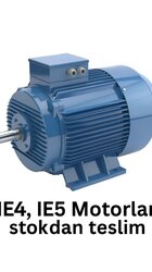
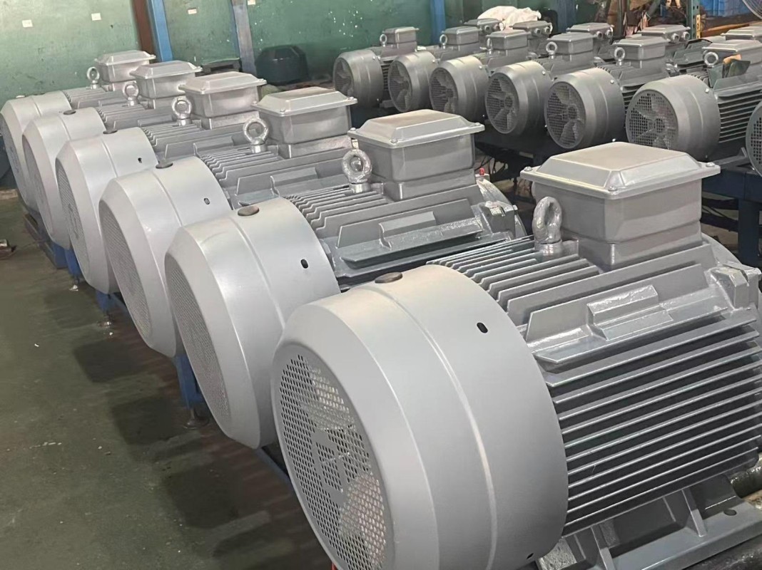

Choosing a motor no longer stops at power and speed. Where production lines are expected to be measurable and remotely manageable, the sensing, drive and communication layer around the machine has become part of the specification.
What a Smart Motor Really Is
The term describes measurement and communication units placed inside or beside the mechanical body so the machine can report its own condition continuously. A plain squirrel cage motor only turns and produces torque. Add sensors for vibration, temperature and current, and the same machine reports bearing wear, load imbalance and winding heating well ahead of a breakdown.
The frame is still cast iron or aluminium and the rotor is still a squirrel cage. Existing IE3 machines can therefore be brought into digital monitoring by fitting a module afterwards.
The Sensor Layer
- Bearing temperature: PT100 or PTC devices watch the drive and non-drive end, raising a warning long before the 155 °C limit of F class insulation is approached.
- Winding temperature: thermistors embedded in the stator catch heating from overload or a lost phase early.
- Vibration: axial and radial readings expose imbalance and coupling misalignment.
- Current and voltage: phase current analysis on a 400 V / 50 Hz supply identifies faults such as a broken rotor bar through signature analysis.
Collected data travels through a field PLC or an edge device into plant software, with Modbus RTU, Profinet or OPC-UA standardising the transfer.
The Drive as Sensor and Saving
Most installations of this kind are built around a frequency inverter. The drive runs the machine off the fixed 400 V / 50 Hz line frequency and reads current, speed and torque internally at the same time. On quadratic loads like pumps or fans, cutting speed by 20 percent can nearly halve power consumption. In variable-flow systems the inverter is both the data source and the saving.
What Predictive Maintenance Changes
Predictive work replaces "repair after failure" and "replace by calendar" with intervention driven by measurement. If bearing vibration on a conveyor motor climbs gradually over several weeks, the system shows the trend and the spare part is ordered on plan. On S1 continuous duty machines that turn through most of a year, the effect on production losses is visible.
Monitoring Proves the Efficiency
Efficiency classes under IEC 60034-30-1 run from IE1 to IE5 and fix how much a motor loses. Monitoring confirms that a high-efficiency machine keeps its efficiency in the field, because load profile, power factor and real consumption are measured continuously. Moving a 30 kW motor from IE2 to IE3 saves several thousand kilowatt-hours annually by itself; the monitoring layer produces the number that proves it.
Mechanical Specification Stays Intact
Fitting monitoring modules costs nothing mechanically. IP55 protection, F class insulation and B3, B5 and B14 mounting remain standard, across a 0.55 kW to 355 kW range with two-pole 3000 rpm, four-pole 1500 rpm and six-pole 1000 rpm options. Sensor cabling leaves through a connection point set beside the terminal box.
Commissioning and Calibration
A monitoring system is only as good as sensor placement and threshold setting. A vibration sensor mounted loosely, or in the wrong spot, reports a value that means nothing. During commissioning the machine is recorded unloaded and loaded to establish a healthy-running reference; later readings are compared against it and the alarm level rises with the deviation. Thresholds are defined against the F class limit and the bearing manufacturer's figures.
Rolling It Out in Stages
The investment does not have to cover the whole plant at once. Running hour records also leave objective data for warranty and service discussions. Pick the three drives that hurt most when they stop, instrument those, and let their first quarter of trend data decide how far the rollout goes.