 English
 Le français
 Türkçe

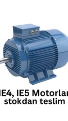
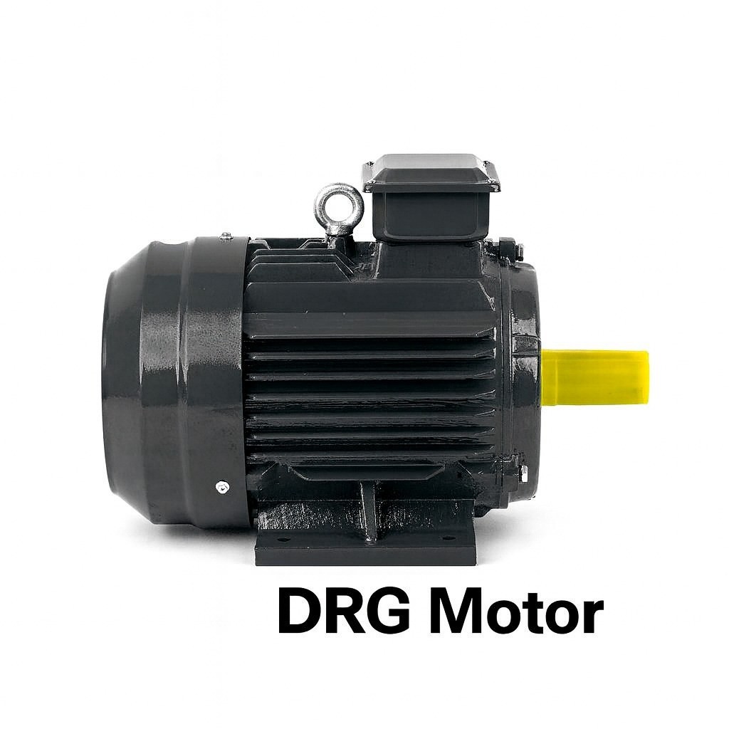

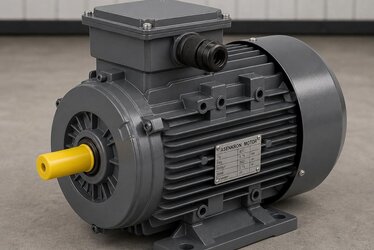
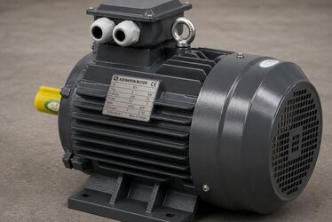
An efficiency class describes one thing only: what share of the drawn electricity leaves the shaft as mechanical work. IE3, IE4 and IE5 are the three steps at the top of that ladder, and every one of them shows as a line on the yearly energy bill wherever it is installed.
What the Classes Actually Measure
Some of what the supply delivers turns into heat: winding resistance gives copper loss, the core gives hysteresis and eddy-current loss, then come friction and windage, and stray load losses. What survives comes off the shaft. The IE classification sets the minimum efficiency permitted for a given rating and pole count. IE1 is standard, IE2 high, IE3 premium, IE4 super premium, IE5 ultra premium.
Reading IEC 60034-30-1 Correctly
The measurement rules and the limit values come from IEC 60034-30-1. The standard covers single-speed three-phase machines from 0.12 kW to 1000 kW and draws separate limit curves for 2, 4, 6 and 8 pole designs. This matters more than it looks: the same machine faces a different threshold at 4 poles, 1500 rpm, than it does at 2 poles, 3000 rpm. Saying "it is IE3" without stating rating, pole count and the 50 Hz supply condition says almost nothing.
The Gap Between the Three Top Classes
In percentage points the steps look small, and in annual energy they do not. On an 11 kW 4-pole machine, IE3 sits at roughly 91.4 percent and IE4 at about 92.6 percent, with IE5 higher still. The spread is wider at low ratings and narrows as power grows.
- IE3, premium: the default across most industry. Balanced cost and efficiency on conveyors, compressors, fans and pumps.
- IE4, super premium: lines that run 16 to 24 hours under continuous load recover the premium faster.
- IE5, ultra premium: lowest losses, generally synchronous reluctance or permanent-magnet designs, normally paired with a drive.
How the Extra Efficiency Is Engineered
More copper of better quality in the winding pushes copper losses down. Fine-grain, low-loss silicon steel cuts iron losses. A longer core stack, optimised slot geometry and accurate rotor balancing add the rest. Copper injection instead of aluminium in the squirrel-cage rotor is the usual route to IE4 and above. Each step makes the machine slightly heavier and dearer, and the energy saved over its working life more than covers the difference.
A Worked Annual Figure
Take a 30 kW motor running 6000 hours a year. At IE2 the efficiency is 91.4 percent, at IE3 it is 92.7 percent. Drawn power differs by the gap between 30 / 0.914 and 30 / 0.927, which comes to roughly 2700 kWh a year. Multiplied by the unit energy cost, the extra investment usually clears in two to three years. On large continuous drives it clears sooner.
Typical Specification
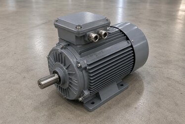
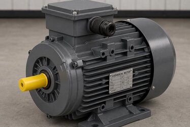
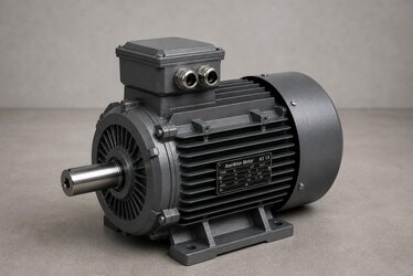
- Cast iron frame, able to take heavy-industry vibration and mechanical shock.
- IP55 rating: dust-tight against harmful ingress, sealed against water jets.
- Winding insulation in class F, 155 °C, limited in service to a B rise, which leaves thermal reserve.
- S1 continuous duty at rated output.
- 400 V / 50 Hz supply; B3 foot, B5 and B14 flange mounting.
- 0.55 kW to 355 kW, with 2, 4 and 6 pole speed options.
Running IE4 and IE5 on a Drive
These classes give up most of their potential only when a frequency converter varies the speed. On pumps and fans, where load follows roughly the cube of speed, dropping speed by 20 percent can halve the power. Inverter operation brings shaft currents and voltage spikes, so bearing specification and winding insulation both have to suit inverter service.
The Curve at Partial Load
The figure stamped on the plate belongs to full load only. Real machines spend most of their time between 50 and 75 percent load. An IE1 motor falls away quickly at half load, while IE3 and IE4 designs hold a high efficiency curve across a wide band. Oversizing destroys that advantage: matching motor size to the actual load counts for as much as the class stamped on the plate.