English
 Türkçe

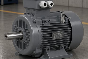
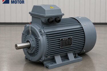
When an electricity bill comes in higher than expected, the first remedy that comes to mind is usually to swap a single component, the motor, for a more efficient model. Yet an electric motor cannot be considered in isolation from the load it turns, the drive that feeds it, and the transmission elements that carry power to the load. Real savings appear only when you treat these components not one by one, but as a whole system that talks to itself. In this article we look at how to evaluate the motor, the frequency inverter, the transmission and the load as a single optimization problem, how losses are distributed across the system, and why a well-engineered drive-and-motor pair delivers far more than a standalone motor replacement ever could.

What is system efficiency, and how does it differ from component efficiency?
Component efficiency describes how well a single part performs within its own boundaries. The IE3 or IE4 class printed on a motor's nameplate tells you how efficient that motor is at a given load. System efficiency, on the other hand, is the product of every link in the chain: electricity drawn from the grid is processed in turn by the drive, the motor, the coupling, the gearbox and finally the load. At each stage some energy turns into heat and is lost. The weakest link in the chain can overshadow the contribution of even the most efficient motor. That is why, when evaluating a system, you should not measure individual component efficiencies but the ratio of useful end-to-end energy delivered to the energy drawn from the grid. This ratio is the number that determines real operating cost.
In practice, when you map a plant's energy use you often find that a handful of large motors account for a significant share of total consumption. Treating each of these motors through a system lens delivers results far faster than scattered small improvements. System thinking is the way to direct resources to the point that pays back the most.
Why is replacing the motor alone not enough?
Buying a high-efficiency motor is the right move, but if the motor does not run at constant speed and continuous full load, the gain remains limited. In many applications the load sits at partial load for much of the time; in that case a motor spinning uncontrolled at full speed simply wastes energy that is not needed. The system approach asks when, at what speed, and with what torque the motor actually has to run.
What does the frequency inverter add to the system?
The frequency inverter adjusts the motor's speed to the real demand of the load. Especially with variable-demand loads such as pumps and fans, lowering the speed a little brings a much larger reduction in power consumption. This happens because in such loads the power requirement does not change in direct proportion to speed but with a much steeper relationship; therefore reducing speed to match the need is far more economical than throttling with a valve or a damper. We covered the details in our article on how a frequency inverter saves energy. The drive is the brain that makes the motor part of the system; without it the motor can only run in two states, on or off, whereas with it the motor continuously adapts to the needs of the process.
Knowing the load: the starting point of optimization
Every optimization begins by understanding the character of the load. Is it constant torque or variable torque? Continuous or start-stop? Sizing done without profiling the load relies on guesswork, and guesswork usually errs on the safe side, meaning oversized.
The hidden cost of oversizing
A motor chosen large "just in case" runs at reduced efficiency and power factor at partial load. As we detailed in our article on the oversized motor partial-load trap, the extra power you buy raises both the initial investment and the operating cost. Correct sizing is the cornerstone of system optimization.
Transmission elements: coupling, gearbox and belt
Every mechanical connection between motor and load is an efficiency stage. If alignment is off, belt tension is wrong, or the gearbox is mismatched to the load, even the most efficient motor gives back what it gained at this stage. System optimization must include the mechanical transmission.
How are losses distributed across the system?
In a motor-drive system, losses are distributed as copper losses, iron losses, friction-and-windage losses and the switching losses of the drive. We examined the origin of the losses on the motor side in our article on where efficiency losses come from. A system view makes each loss type separately measurable.

Copper losses and conductor quality
The quality and cross-section of the copper in the windings directly affect the resistive losses that arise under load. In our article on rotor copper-wound electric motors we explained how conductor choice contributes to efficiency. In system optimization the internal design of the motor is also taken into account.
Iron losses and lamination quality
The magnetic quality of the steel that forms the stator and rotor stack determines the iron losses. We addressed this in our article on the effect of low-loss electrical steel on motor efficiency. Thin, low-loss lamination is decisive, especially in the higher efficiency classes.
Power factor and reactive load
The system must manage not only active power but also reactive power. A low power factor increases the current drawn from the grid and creates extra losses in the cables. The frequency inverter and correct sizing improve the power factor and deliver benefit across the whole system.
Cable length and voltage spikes
As the cable between drive and motor grows longer, the switching pulses can lead to reflected waves and voltage overshoots. We explained this phenomenon in our article on dv/dt and reflected waves in long motor cables. In system design, the cable too is a component.
Shaft voltage and bearing currents
In drive-fed motors, voltage can build up on the shaft and currents passing through the bearings can cause damage. Our article on VFD shaft voltage and bearing currents deals with this in depth. System optimization protects not only energy but also the life of the motor.
Soft starting and mechanical stress
Direct-on-line starting creates high current and a mechanical shock at start-up. Soft starting, or controlled start through the drive, protects both the grid and the transmission. We detailed this gain in our article on the advantages of soft starting.
Insulation class and thermal endurance
When system optimization runs the motor more frequently and more flexibly, the thermal endurance of the insulation gains importance. Our article on electric motor insulation class explains which class withstands which operating temperature.
Process quality improving through speed control
The gain from optimization is not only energy. Correct speed control also improves product quality, repeatability and machine life. A mixer turning at the right speed or a belt slowing to match demand directly affects the process output.
No optimization without monitoring
You cannot improve what you cannot measure. Energy monitoring shows which machine consumes how much and where the savings potential lies. We described monitoring strategies in our article on energy monitoring in electric motors.

Reading the nameplate correctly
To understand a motor's role in the system you have to read its nameplate. Our article on reading the IE class from the motor nameplate shows what each value means. Efficiency class, power, speed and power factor are the inputs of the system calculation.
Where high-efficiency motors fit in the system
When the system is optimized, a high-efficiency motor shows its full potential. In our article what is a high-efficiency motor we discussed the differences between IE3, IE4 and higher classes. The motor is the most critical component at the heart of the system.
Frame material and mechanical stability
The material of the motor frame affects system performance in terms of vibration damping and heat dissipation. In our article on the cast iron electric motor we explained the advantages of a cast frame. A solid frame behaves more stably under the dynamic operation imposed by the drive.
The system approach in industrial applications
From pumping stations to conveyors, from compressors to cranes, every application has its own load profile. In our article on industrial electric motors we covered the requirements of different sectors. The system approach produces a different recipe for each application.
Special cases in lifting and crane applications
In lifting applications the motor can behave like a generator while the load descends; this situation calls for a dedicated solution in terms of braking and energy management. We examined these scenarios in our article on crane and lifting electric motors. System optimization also opens the door to energy recovery in these applications.
The role of maintenance and service in the system
A well-built system loses its efficiency over time if left without maintenance. Factors such as bearing wear, lost alignment and clogged filters increase losses. Planned maintenance keeps the optimization permanent.
Making service decisions with data
Monitoring data tells you when to intervene. Trends in current, vibration and temperature give warning before a fault occurs. The system approach makes the shift from reactive to predictive maintenance possible.
How much is the savings potential?
The savings potential varies by application; in a variable-load system, the drive together with correct sizing can deliver a significant energy reduction through an integrated approach. The key is to distribute the gain not to a single component but to the whole system. The figures here are general in nature; the real gain becomes clear with measurement.
Calculating the payback period correctly
The investment decision should be made by looking not only at the price of the motor but at the drive, the installation and the expected energy gain. The payback period of a system-wide improvement is often more predictable than that of a single-component swap.
Standards and compliance
Efficiency classes and measurement methods are defined by international standards. Choosing a motor and drive that comply with these standards guarantees both legal compliance and comparable performance. Adherence to standards in system design lays a sustainable foundation.
Cooling and environmental conditions
Conditions such as ambient temperature, altitude and dusty environment affect the power a motor can deliver and its cooling need. The system calculation must include these environmental factors; otherwise the expected efficiency cannot be achieved in the field.
Harmonics and grid quality
Drives can emit harmonics into the grid. Choosing the right filter and topology both protects grid quality and prevents extra losses. System optimization goes beyond the motor and also watches over the electrical health of the facility.
The human factor and operating habits
Even the best system cannot show its potential when operated incorrectly. Operator training, correct set points and the prevention of needless running form the human side of optimization. Technology and habit must be improved together.
A step-by-step optimization road map
First profile the load, then measure current consumption through monitoring. Identify oversizing, assess drive applicability, check the mechanical transmission, and finally match the motor with the appropriate efficiency class. Proceed by measuring the gain at every step.
From pilot application to roll-out
Rather than changing an entire system at once in a large facility, starting with the heaviest-consuming machine as a pilot is a risk-free path. The gain verified in the pilot puts the roll-out decision on a solid footing.
Fine-tuning the drive programming
After the frequency inverter is installed, the acceleration ramps, carrier frequency and protection thresholds must be matched to the load. A wrong parameter both lowers efficiency and stresses the motor. Fine-tuning is often the most overlooked yet most profitable stage of system optimization.
Redundancy and continuity
In critical processes, optimization must be done without compromising continuity. A spare-motor strategy and drive bypass options balance energy gain with operational safety.
Measurement-based reporting
To demonstrate the value of an improvement, before-and-after consumption must be reported. Transparent reporting both justifies the investment and guides the next improvement.
The choice of speed and its effect on the system
The same power can be produced with different pole numbers, that is at different speeds. Matching the speed the load actually needs with the motor's rated speed can eliminate the losses caused by an unnecessary gearbox or by reducing speed with a belt. When direct drive is possible, the number of transmission stages drops and system efficiency rises. The choice of speed is therefore a design decision not only of the motor but of the entire transmission chain.
Operating regime and duty cycle
Whether a motor runs continuously or intermittently is critical data that determines the correct selection. The needs of a continuously running fan and a conveyor motor that starts and stops hundreds of times a day are very different. When the duty cycle is assumed incorrectly, the motor is either chosen too large and runs inefficiently at partial load, or too small and overheats. The system approach clarifies the duty cycle with measured data and makes the selection accordingly.
Thermal balance and continuous power
The power a motor can deliver is ultimately limited by its ability to dissipate the heat it produces. If cooling is adequate the motor stays stable at its rated power; if cooling is insufficient the insulation ages quickly. In self-cooled motors running at low speed through a drive, the fan also slows so cooling weakens; this may require a separate cooling solution in the system design. An optimization that ignores thermal balance gains on paper while stealing from motor life in the field.
The importance of working with the right partner
Working with a supplier who knows the motor, the drive and the application together ensures that the parts of the system are compatible with one another. A single-source solution prevents responsibility from being divided and makes it easier to get results in the field.
DRG Motor for system-level efficiency
Optimization is not a one-off project but a continuous perspective. Asking "where does this part stand within the system?" with every new machine purchase and every revision brings the greatest gain over the long term. Seeing your motor not merely as a motor but as the heart of the whole raises energy and process efficiency together. At DRG Motor we stand by you to help you select our IE3, IE4 and IE5 efficiency-class induction motors according to your application's load profile and drive setup; to match the right motor with the right system, get in touch with us.