English
 Türkçe
Shaft Voltage and Bearing Currents in VFD-Driven Motors
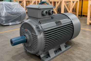
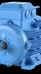
Driving an asynchronous motor with a frequency inverter (VFD) brings major advantages in energy savings and flexible speed control. Yet the fast, switched voltage waveform produced by the inverter introduces a new mechanism that never appears on a classic motor fed directly from the mains: shaft voltage and, as a result, bearing current. When this phenomenon goes unnoticed, the bearing of an apparently healthy motor is quietly destroyed within months, leading to an unexpected shutdown. At DRG Motor, this article explains in detail how inverter-induced bearing current arises in our IE3/IE4/IE5 efficiency-class asynchronous motors, the symptoms by which it reveals itself, and the practical measures that prevent it.

The Root Cause: What Is Common-Mode Voltage?
Mains voltage is a symmetrical three-phase sine wave, and the instantaneous sum of the three phases is ideally zero. A frequency inverter, however, generates its output voltage with fast-switching semiconductor devices using pulse-width modulation (PWM). In this pulsed structure the instantaneous sum of the three phases is no longer zero; a component that oscillates with respect to ground appears. This oscillating component, seen between the motor's star point and ground, is called common-mode voltage.
Common-mode voltage changes in steps with every switching event of the inverter. Its frequency is high and its rise time is extremely short. This rapid change travels through the small capacitances inside the motor and reaches the shaft and the bearings. The problem is therefore not mechanical but purely electrical in origin, and it is a natural by-product of how the frequency inverter works.
How Does Shaft Voltage Form?
Inside an asynchronous motor there are very small but real parasitic capacitances between the stator winding and the rotor, between the rotor and the frame, and between the winding and the frame. The common-mode voltage acts across these capacitances like a voltage divider. As a result, the rotor shaft rises to a certain voltage relative to the frame (ground). This is called shaft voltage.
Shaft voltage on its own may seem harmless, because it is fed from a tiny capacitance and draws no load. However, the rotor's attempt to discharge this voltage through the bearings starts the chain that causes the real damage.
The Oil Film and the Insulation Barrier
In a running motor, a thin oil film exists between the bearing balls and the raceways. This film not only reduces friction but also behaves as a weak insulator. As long as the shaft voltage stays low, the film holds the voltage as a barrier and no current passes.
The problem begins when the shaft voltage exceeds the withstand limit of the oil film. When the film thins at low speed, or while the motor has not yet fully warmed up, this threshold is crossed more easily. The instant the threshold is exceeded the film breaks down and the stored energy releases in a sudden spark.
EDM Current: The Mechanism of Electrical Erosion
This sudden discharge through the broken-down oil film is called electrical discharge machining current, or EDM current for short. It takes its name from the spark-erosion method used in metalworking, because the mechanism is identical. With every discharge a microscopic spark tears off and melts a tiny amount of metal from the bearing surface.
A single discharge is insignificant. But the inverter switches thousands of times per second, and the shaft voltage pierces the oil film again and again. This constant repetition forms millions of tiny craters on the surface, slowly eroding the raceways and the balls. The damage is invisible at first but cumulative.

Fluting: The Characteristic Signature of the Damage
When the EDM current continues long enough, fine lines appear at regular intervals along the raceway. This pattern, resembling the teeth of a comb or a washboard, is called fluting. Fluting is the most characteristic and almost certain fingerprint of inverter-induced bearing current.
Once fluting forms, the bearing no longer rotates smoothly. The balls catch and jump across these grooves, which leads to rapidly rising vibration and a characteristic humming noise. From this point on the damage is irreversible and replacing the bearing becomes unavoidable.
Grey Grease: The Early Warning Sign
Before the damage becomes visible there is usually a warning signal: a change in grease colour. Each time the EDM current discharges, the microscopic metal particles it tears off and the heat of the spark burn the grease. Over time the normally light-coloured grease takes on a dark grey, even near-black colour.
During a motor's maintenance, grease that comes out unusually grey and metallic almost always signals electrical discharges. For this reason, grease colour is an indicator that must always be checked in predictive maintenance programmes.
How to Recognise the Symptoms
On an asynchronous motor driven by an inverter, seeing the following symptoms together is a strong reason to suspect shaft voltage and bearing current:
- Premature bearing failure: repeated bearing replacement far sooner than expected.
- Characteristic hum: an electrically originated sound that varies with speed and differs from mechanical imbalance.
- Rising vibration: an oscillation that grows as fluting develops and does not respond to noise and vibration reduction measures.
- Grey grease: darkened, metallic grease noticed during maintenance.
- Appears only on inverter operation: if the same motor runs flawlessly straight from the mains, the inverter is to blame.
Which Bearing Is Affected More?
Usually the bearing at one end of the motor is stressed more than the other. The reason is that the current path discharging the shaft voltage is not distributed symmetrically between the two bearings. The high-frequency current chooses the path of least resistance and discharges through the bearing on that path. As a result, the damage often concentrates in a single bearing.
The Relationship Between Motor Size and Risk
The shaft voltage problem is closely linked to motor size. In large-frame, high-power motors the parasitic capacitances are larger and the surfaces between shaft and frame are wider. For this reason, high-kW three-phase industrial motors face a markedly higher bearing-current risk when driven by an inverter. While the risk is lower in small motors, it should still be considered in continuously running applications.
Protection Method 1: The Shaft Grounding Ring
One of the most effective and common measures is to offer the voltage accumulating on the shaft a low-resistance escape path that bypasses the bearings. A shaft grounding ring does exactly this. A conductive ring placed around the shaft discharges the shaft voltage directly to the frame and ground, without ever passing through the bearing.
When the current flows through this ring instead of the bearing, the oil film is never pierced, no EDM current forms, and fluting damage is prevented. The grounding ring is a practical solution that can also be retrofitted to existing motors.
Protection Method 2: Insulated and Ceramic Bearings
The second approach is to physically cut the path the current would take. An insulated bearing has its outer race covered with an insulating coating that blocks the passage of electrical current. A ceramic bearing has balls made of insulating ceramic and cuts the current entirely at the ball level.
These bearings are preferred especially in high-power motors. One point needs attention, however: if only one end of the motor is insulated, the current may redirect to the bearing at the other end. The solution must therefore be planned holistically.

Protection Method 3: Common-Mode Choke and Filters
Another method that addresses the source of the problem is to reduce the common-mode voltage from the very start. A common-mode choke placed at the inverter output is a coil that wraps all three phases together and presents high impedance to high-frequency common-mode current. In this way the voltage reaching the shaft is largely damped.
Waveform-correcting filters added on the output side also reduce both common-mode and phase-to-phase stress. These filters likewise protect against another problem that appears on long cables, the voltage spikes that stress the insulation class.
Correct Grounding and Cabling
As much as the hardware measures, the quality of grounding in the facility is decisive. A low-impedance, short and wide-cross-section grounding connection between the motor frame and the inverter lets the high-frequency current find the right path. The shield of a screened motor cable must be terminated properly at both ends. Neglected grounding can render even the best bearing protection ineffective.
What to Watch During Maintenance
During the periodic maintenance of inverter-driven motors, a few extra checks help catch the problem early:
- Grease colour check: darkening and a metallic sheen are signs of electrical discharge.
- Vibration monitoring: tracking the vibration trend with energy and condition monitoring.
- Bearing replacement history: recording repeated failures.
- Grounding measurement: regular inspection of connection resistances.
When these checks become a natural part of the motor maintenance steps, costly shutdowns are avoided.
The Advantage That Comes From Design
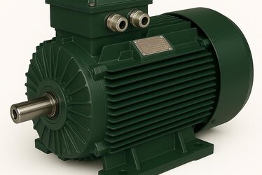
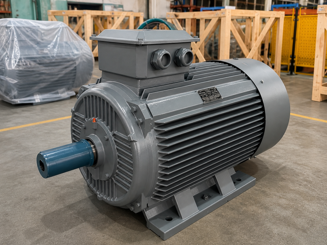
The most lasting protection against bearing current is designing the motor to run on an inverter from the outset. An asynchronous motor built with quality insulation materials, balanced capacitances and suitable bearing options causes far fewer problems in the field. DRG Motor's IE3/IE4/IE5 class motors are offered with the requirements of modern inverter-driven applications in mind.
Asking the Right Question: Motor or System?
Bearing current is a matter for the whole drive system, not a single component. Inverter selection, cable length, grounding, filters and bearing type must all be addressed together. Trying to solve the problem by merely replacing the bearing means the same fault will return shortly. The lasting solution is a holistic engineering approach.
The Role of the Switching Frequency
The semiconductor switches of the inverter open and close thousands of times per second, and this speed is called the switching frequency. A higher switching frequency makes the motor current smoother and reduces noise; but because it also produces more pulses per unit of time, it increases the high-frequency energy reaching the shaft. Raising the switching frequency can therefore improve motor sound while slightly increasing the bearing-current risk. The correct setting should be made considering the whole system, choosing a balanced point between sound, efficiency and bearing life.
Insulation and Bearing Current Must Be Considered Together
Inverter supply stresses not only the bearings but also the winding insulation. The high-frequency voltage reaching the shaft and the voltage spikes that stress the first turns of the winding both arise from the same source, the pulsed output voltage. So when choosing a motor suitable for an inverter, both bearing protection and insulation strength must be evaluated together. Improving only one may let the problem return from the other end; a holistic view extends the total life of the motor.
The Difference Between Mains Supply and Inverter Supply
In an asynchronous motor fed directly from the mains, the voltage follows a smooth, continuously changing sine curve. There are no sudden jumps in this curve, so no significant high-frequency voltage forms between shaft and frame. When the same motor is connected to an inverter the situation changes completely, because the output voltage now consists of thousands of sharp pulses. This pulsed structure is the one and only true culprit of bearing current. For this reason a motor that has run flawlessly on the mains for years can begin to suffer bearing failures shortly after being moved to an inverter.
Load Type and Operating Speed Effect
The shaft voltage problem is also affected by the speed at which the motor runs. At low speed the oil film in the bearing thins and its insulating strength drops, leading to more frequent discharges. Pump and fan applications that run over a wide speed range, especially for long periods at low speed, therefore carry a higher risk. While the risk is relatively lower in a motor running continuously at a fixed high speed, long running hours still increase total damage.
The Cost of the Damage: Visible and Invisible Losses
The cost created by bearing current is not only the price of the replaced bearing. The real major cost is the damage that unplanned shutdowns do to production. An unexpected motor failure on a continuously running line means hours of lost production, an emergency service call and delivery delays. Add to this the fluting damage progressing to affect the shaft and other parts, and it becomes clear how valuable a small precaution is. The right protection method is often far cheaper than the cost of the first failure. Moreover, protection that is correctly installed once pays back again and again over the motor's entire service life.
How to Prioritise the Measures
It is not necessary to take every measure at once in all applications. In low-power installations with short cables, good grounding and a suitable motor choice are usually enough. In medium- and high-power systems that run long hours, a shaft grounding ring is a strong choice. In very high-power and critical applications, using an insulated bearing, a grounding ring and an output filter together is the safest path. The right combination is shaped by the motor's power, the cable length and the operating profile.
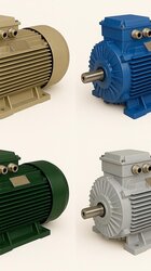
DRG Motor for Inverter-Ready Solutions
In your frequency-inverter applications, choosing the right motor is the first and most important step to minimising the risk of shaft voltage and bearing current. At DRG Motor, we stand by you with our IE3/IE4/IE5 efficiency-class asynchronous motors and application support. For the most suitable motor type, bearing protection and mounting solution for your drive system, explore our electric motor products and reach our technical team via drgmotor.com. To better understand inverter-induced issues in asynchronous motors, we also recommend reading our what is an electric motor and industrial electric motors content.