 English
 Le français
 Türkçe


160 kW 1500 RPM Three Phase Motor – Coupling, Transmission and the Rewind Decision
A 160 kW frame is never the whole drive. It reaches the machine through a coupling, a gearbox or a belt set, and the way that transmission is arranged decides more about the motor's life than its own specification does. A four-pole machine of this size turning near 1500 RPM puts a large torque through a small interface, and everything downstream of the shaft has to be built for it.
A second question arrives later, when the machine faults: rewind it or replace it. On a 160 kW drive that decision is worth more than the gap between any two quotations, and it is answerable only if the right information was recorded when the motor was new.
The 160 kW Frame and What It Drives Through
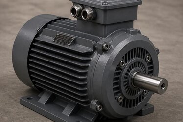
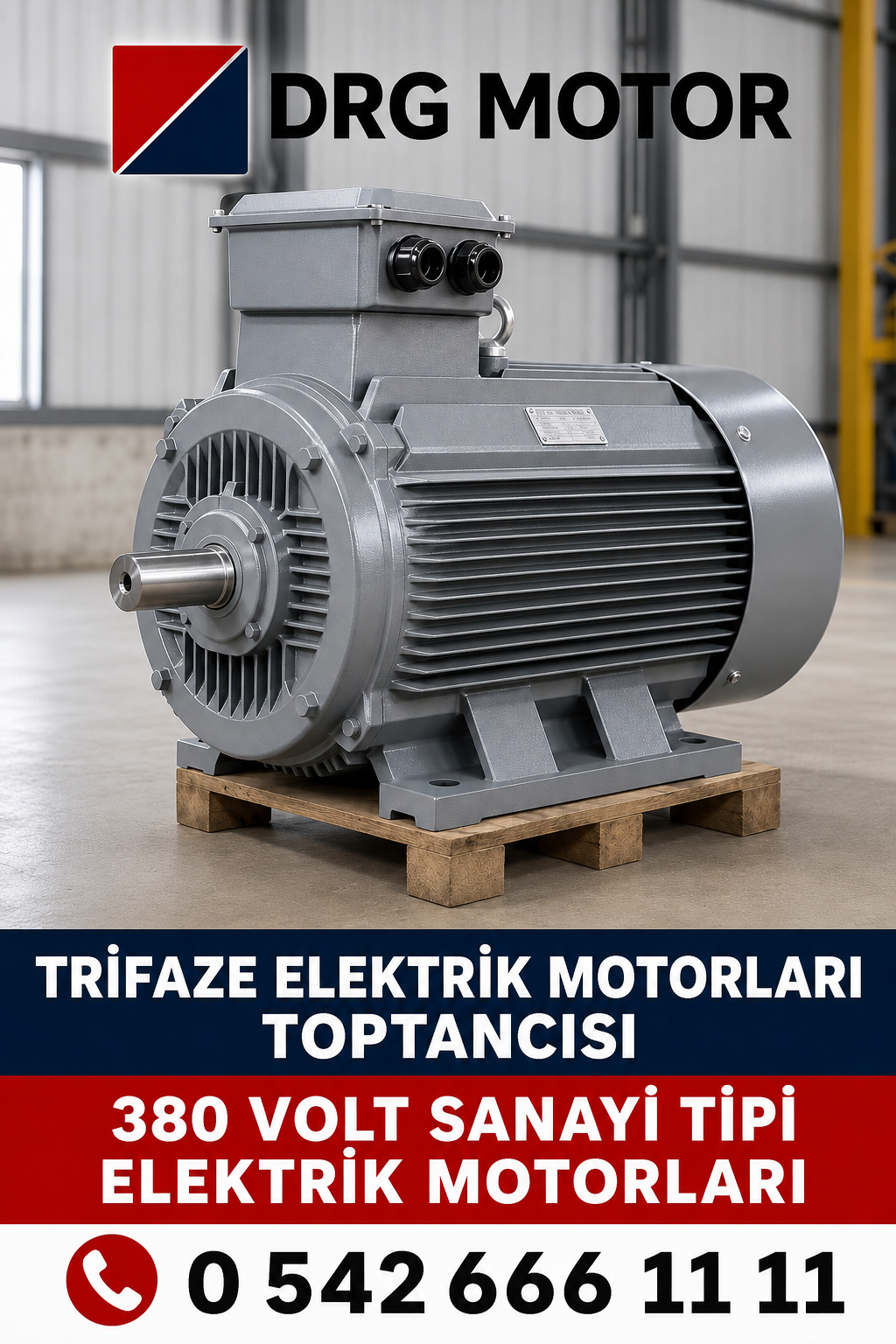
A 160 kW four-pole three-phase induction machine at 380–400 V, 50 Hz turns near 1500 RPM in a heavy cast iron frame. The shaft is sized for the torque that rating implies, and the coupling, the key and the gearbox input have to be sized for the same figure — including the peak the driven machine demands at start, which is higher than the running torque.
Where the transmission is undersized the motor survives, and the coupling, the key or the gearbox does not.
Coupling and Transmission Arrangements
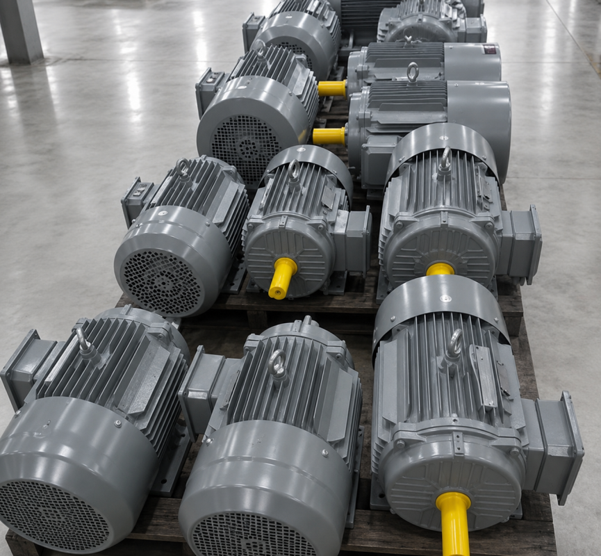
A handful of arrangements cover almost every 160 kW installation, and each puts a different demand on the shaft and the drive-end bearing:
- Direct coupling to the driven machine through a flexible element
- Coupling with a torque limiter where the load can jam
- Fluid coupling where the torque has to build up gradually
- Flange-mounted to a gearbox input, with no coupling at all
- Gearbox with a hollow shaft fitted over the motor shaft
- Belt drive with multiple V-belts on a machined pulley
- Belt drive on slide rails, so tension can be set and reset
- Overhung load calculated wherever a pulley is fitted
- Guard designed to allow alignment checks without full removal
- Shaft key and keyway sized for the torque being transmitted
- Coupling bored and keyed to the motor shaft, not adapted to it
- Foundation stiff enough to hold alignment under load
- Slide rails where belt tension has to be adjusted in service
Whichever is used, alignment is set cold and rechecked once the drive has run warm, and the first reading is written down rather than remembered.
Technical Data
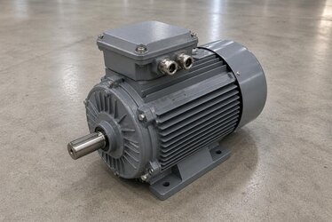
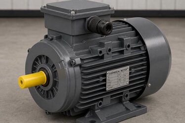
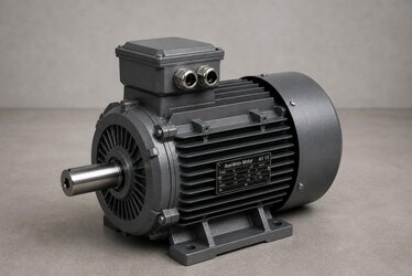
The 160 kW three-phase machine is built to IEC dimensions in a heavy-duty cast iron frame for continuous industrial duty.
Main Technical Features
- Power Output: 160 kW
- Speed: 1500 RPM
- Four-pole design
- Three-phase induction motor
- Operating Voltage: 380–400 V
- Frequency: 50 Hz
- IE3 Premium Efficiency
- IE4 Super Premium Efficiency options
- 100% copper windings
- Heavy-duty cast iron frame
- IP55 protection
- Class F insulation
- Low vibration
- Low noise operation
- Long-life bearings
- Continuous duty operation
- IEC compliant design
- B3 foot-mounted version
- B5 flange-mounted version
- B35 foot and flange-mounted version
Overhung Load and Belt Drives
A belt drive puts a side load on the motor shaft that a direct coupling does not. At 160 kW that load is substantial and it is carried by the drive-end bearing rather than by the frame. Pulley diameter, belt tension and how far the pulley sits from the shaft shoulder together decide how long that bearing lasts.
Where the layout allows it, flange-mounting a gearbox removes the belt, the pulleys, the tension adjustment and the side load in a single decision, and removes the transmission losses with them.
Driven Machines and How They Are Coupled
The 160 kW rating drives main plant equipment, and the transmission usually follows from the machine:
- Primary crushers, driven by V-belt sets on slide rails
- Screening plants, driven through flexible couplings
- Concrete plant mixers, flange-mounted to a gear unit
- Cement mills, coupled through a reduction gearbox
- Mine hoists, geared with a brake on the drive train
- Steel plant roll drives, coupled through gear couplings
- Chemical agitators, flange-mounted onto the vessel gear unit
- Petrochemical transfer pumps, close-coupled to the pump
- Food plant line drives, geared with a hollow shaft unit
- Irrigation pump stations, coupled on a common base plate
- Fire pump sets, direct-coupled with a shaft guard
- Trunk main booster pumps, close-coupled to the casing
- Deep well and dewatering pumps, coupled on a vertical head
- Dust extraction fans, driven by belt sets for speed matching
- Boiler draught fans, direct-coupled on a rigid base
- Screw compressors, flange-mounted to the airend
- Centrifugal compressors, coupled through a step-up gear
- Overland conveyors, geared with a backstop fitted
- Shredders, driven through fluid couplings against shock
- Wood chippers, belt-driven with a heavy flywheel
- Extruder main drives, geared with thrust bearing units
- Rubber mixers, coupled through a hard-duty gear unit
- Paper machine sections, geared and speed-controlled
- Ceramic mills, belt-driven onto a girth gear
- Cooling water pumps, close-coupled on a shared skid
Shaft, Bearing Housings and the Cast Iron Frame
At 160 kW the frame has one mechanical job above all others: holding the two bearing housings in line while a large torque reaction tries to twist it. Cast iron is what makes that possible over years rather than months.
What that means for the transmission:
- Bearing housings that stay in line under torque reaction
- A shaft that keeps its alignment with the driven machine
- Mass that damps vibration coming back through the coupling
- A drive-end bearing able to take a belt side load
- Dimensional stability through repeated heating and cooling
- A housing that can be lifted and reinstalled without distortion
- Feet that survive being unbolted and shimmed again
Winding Construction and What It Means for a Rewind
The winding is 100% copper, and on a machine this size that matters twice: once while it runs, and once again if it ever has to be rewound.
What the original construction determines:
- The copper section a rewind has to match to hold the class
- The slot fill a repair shop must reproduce
- The insulation system the replacement has to equal
- The temperature the machine ran at before the fault
- Whether the original efficiency class can be recovered
- Whether the rewind is worth doing at all
Rewind or Replace at This Rating
A 160 kW machine is large enough that a rewind is a genuine alternative rather than a false economy. The decision turns on what the failure says and on what the plant wrote down when the motor was new.
What decides it:
- Whether frame, shaft and bearing housings are still true
- Whether the failure was thermal, mechanical or a supply fault
- Whether the original efficiency class can be matched in a rewind
- Copper section and slot fill the repair will actually use
- Whether the insulation system will equal the original class
- Downtime a rewind needs against the lead time for a new machine
- Whether a spare motor exists to cover either route
- Whether the same fault has already happened on this drive
- What the commissioning readings showed when the motor was new
- Whether the driven machine has changed since installation
Recording the Data the Next Decision Will Need
Nearly every question in the list above is easy to answer if the answers were written down on the day the motor was commissioned, and impossible if they were not.
Record these at installation:
- Nameplate data, including efficiency class and rated current
- Frame size, shaft diameter and mounting arrangement
- Coupling or pulley type, with bore and key dimensions
- Transmission ratio where a gearbox or belt set is used
- Alignment figures taken cold and again after running warm
- Base bolt torque applied at installation
- Vibration reading at each bearing, kept as the baseline
- Winding and bearing temperature after the drive stabilised
- Running current at normal production load
- Insulation resistance measured before first energising
- Supply voltage measured at the motor terminals
- Protection and thermal settings as left on the switchboard
- Bearing references and the grease type used
- Ambient temperature and installation altitude at the position
- Duty cycle and the number of starts per hour expected
- Terminal box orientation and cable arrangement as built
- Who commissioned the drive, and where the record is kept
That record costs a morning, and it is what turns every later decision about the drive into an engineering one instead of a guess.
Ordering a 160 kW 1500 RPM Motor from DRG Motor
Send the driven machine and the transmission arrangement — direct coupling, gearbox flange or belt set — and the 160 kW frame is quoted with the shaft, key and mounting confirmed against that interface.
Windings are 100% copper, frames heavy-duty cast iron, protection IP55 and insulation Class F, built to IEC dimensions in IE3 and IE4 efficiency classes.
Ask for the coupling and alignment sheet with the quotation, so the transmission side is settled before the motor reaches site.