 English
 Le français
 Türkçe

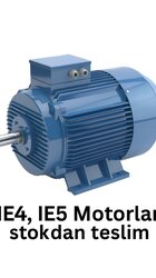

As IEC 60034-30-1 stands today, IE5 sits on its top rung, and it targets a loss level a conventional induction machine cannot reach by tuning alone. Where a drive works all year, the motor itself consumes most of the electricity bill; every step up the ladder therefore shows in annual operating cost.
The Ladder and What Each Step Demands
Low voltage machines are ranked IE1 Standard, IE2 High, IE3 Premium, IE4 Super Premium and IE5 Ultra Premium. Each step requires losses to fall by roughly 15 to 20 percent against the one below. IE3 is already the legal floor above 0.75 kW in many countries; IE5 remains voluntary. On a four pole 7.5 kW machine, IE3 efficiency sits near 90 percent and IE5 climbs past 93 percent.
Where the Losses Actually Live
Total loss breaks into stator copper loss, rotor loss, iron loss in the core, and friction plus windage. Reaching IE5 means attacking every one of those items, not just the largest.
- Thin, low loss silicon electrical steel cuts core loss.
- A higher slot fill factor reduces copper loss; some designs replace aluminium rotor bars with copper.
- Part of the IE5 range drops the squirrel cage for a permanent magnet or synchronous reluctance rotor, taking rotor loss close to zero.
- Optimised fan and bearing selection trims friction and ventilation loss.
Induction Rotor Against Synchronous Rotor
A squirrel cage rotor always lags the rotating field a little. That lag, the slip, induces the rotor current that produces torque, and it produces rotor loss as a by-product. In the permanent magnet and synchronous reluctance architectures common at IE5, the rotor turns at field speed. No slip, and rotor loss largely disappears. The trade is that these machines usually need a frequency converter, so direct on line connection is not always available.
Poles, Speed and the Available Power Band
Speed follows pole count and supply frequency. On a 400 V / 50 Hz network a two pole machine turns at about 3000 rpm synchronous, four pole at 1500 rpm, six pole at 1000 rpm, with induction types running below that by the slip. IE5 units are typically offered from 0.55 kW up to a few hundred kW. Choose the pole count that meets the required speed and torque and a gearbox stage often becomes unnecessary.
Protection and Thermal Class
IP55 covers dust and water jets and satisfies most dusty or damp installations. Winding insulation is commonly F class at 155 °C, held to a B rise so it lasts longer. Continuously loaded drives are specified on S1; processes that stop and start often are assessed against S3 to S6.
Frame and Mounting
Cast iron suits heavy industry, where damping and rigidity both matter; aluminium is lighter and works on smaller equipment. The B3 foot, B5 flange and B14 small flange arrangements are chosen against whatever the shaft has to meet.
Which Duties Repay the Premium
- Continuously running water and wastewater pumping stations
- Ventilation and process fans
- Belt and conveyor drives
- Screw compressor drives
- Machine and line motors already fed by variable speed drives
Two or three hours of running a day is usually better served by IE3. Decide from the real load profile and the annual hours.
The Arithmetic on a 30 kW Drive
Suppose a 30 kW motor runs 6000 hours a year at 92.7 percent in IE3 and 94.2 percent in IE5. Input power is shaft power divided by efficiency: about 32.36 kW against 31.85 kW. That half kilowatt over 6000 hours is roughly 3000 kWh, every year of the machine's life.
Commissioning With a Converter
Because synchronous IE5 machines normally run behind a frequency converter, the drive parameters have to match the motor. Rated current, voltage, frequency and pole data go in from the nameplate; enter them loosely and both efficiency and torque fall short. Windings exposed to switching voltages need reinforced insulation, and bearing current countermeasures belong in the same discussion.