 English
 Türkçe
When to Use Direct-On-Line (DOL) Starting
Direct-on-line starting is the oldest and simplest way to start an induction motor. The motor is connected directly to the line through a contactor and is suddenly energized at ful... More Details

Direct-on-line starting is the oldest and simplest way to start an induction motor. The motor is connected directly to the line through a contactor and is suddenly energized at ful... More Details
The number printed on an electric motor's price tag is only a small fraction of what that motor will actually cost you. An industrial motor runs in your facility for years, often w... More Details
One of the most overlooked details when ordering a motor for a plant is how that motor will actually behave behind a frequency drive. Whether the application is a pump, fan, convey... More Details
When a machine moves from prototype to volume production, the gap between buying a single motor and securing hundreds of motors at the same specification, the same delivery rhythm ... More Details
0.37 kW 1500 RPM Three Phase Electric Motor – Compact, Efficient, and Designed for Reliable Industrial Operation Electric motors are essential components in industrial automation,... More Details
0.55 kW 1500 RPM Three Phase Electric Motor – Compact Size, Energy Efficiency, and Reliable Performance Electric motors are indispensable components in modern industrial systems, ... More Details
0.75 kW 1500 RPM Three Phase Electric Motor – Compact Design, High Efficiency, and Reliable Industrial Performance Electric motors are essential components in modern industrial sy... More Details
1.1 kW 1500 RPM Three Phase Electric Motor – Compact Power, High Efficiency, and Reliable Industrial Performance Electric motors are essential components in modern industrial syst... More Details
1.5 kW 1500 RPM Three Phase Electric Motor – Compact, Efficient and Built for Reliable Industrial Performance Electric motors are the driving force behind countless industrial mac... More Details
2.2 kW 1500 RPM Three Phase Electric Motor – Compact Power with Maximum Efficiency Electric motors are essential components in modern industrial systems, providing the reliable me... More Details
3 kW 1500 RPM Three Phase Electric Motor – Compact Design, Reliable Performance, and High Energy EfficiencyElectric motors are essential components in modern industrial operations,... More Details
4 kW 1500 RPM Three Phase Electric Motor – Compact Size, Reliable Performance, and High EfficiencyIndustrial electric motors play a critical role in ensuring the smooth operation o... More Details
5.5 kW 1500 RPM Three Phase Electric Motor – Reliable Efficiency for Industrial ApplicationsElectric motors are essential components in modern industrial operations, providing the ... More Details
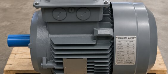
7.5 kW 1500 RPM Three Phase Electric Motor – Efficient Industrial Power for Every ApplicationIndustrial machinery requires dependable power to maintain productivity and ensure unin... More Details
11 kW 1500 RPM Three Phase Electric Motor – Reliable Power for Industrial ApplicationsEvery industrial production facility depends on reliable equipment to maintain productivity an... More Details
15 kW 1500 RPM Three Phase Electric Motor – Premium Industrial Performance with High Energy EfficiencyThe demand for reliable industrial electric motors continues to increase as ma... More Details
18.5 kW 1500 RPM Three Phase Electric Motor – A Reliable Solution for Continuous Industrial OperationSelecting the right electric motor is one of the most important decisions for a... More Details
22 kW 1500 RPM Three Phase Electric Motor – Reliable Power for Industrial PerformanceA dependable electric motor is one of the most important investments for any industrial facilit... More Details
55 kW 1500 RPM Three Phase Electric Motor for Industrial ApplicationsWhen searching for 55 kW 1500 RPM electric motor prices, industrial buyers are generally looking for a solution... More Details
45 kW 1500 RPM Three Phase Electric Motor for Reliable Industrial PerformanceModern industrial facilities depend on electric motors that can operate continuously while maintaining ... More Details